MAINTENANCE | ||
| ||
|
|
|
Wire Feed Speed Validation | To change the wire feed speed calibration: |
|
Return to Section TOC
Return to Section TOC
to Section TOC
Return to Master TOC
Return to Master TOC
to Master TOC
(See Figure D.1)
Calibration of the
Tools required:
•RPM meter
•Constant voltage DC welding power source
•7/16" open end wrench
To verify if calibration is necessary:
1. | Turn power OFF. |
| |
2. Set the wire feed speed per the table. | |||
|
|
| |
Model gearing | Wire Feed Speed | Acceptable Range | |
Normal Speed | 400 in/min | 69 - 77 rpm | |
Extra Torque | 150 in/min | 25 - 31 rpm | |
3. | Remove the plastic cover from the lower portion of the | ||
| wire drive with a 7/16" wrench. |
| |
4. | Connect the | ||
| welding power source. The work lead of the | ||
| PRO must be connected to the work terminal of the | ||
| power source. |
| |
5. | Turn power ON. |
| |
6. | Measure the motor rpm when the COLD FEED button | ||
| is pressed. |
|
|
7. Verify the rpm is within the acceptable range.
(See Figure D.2) Tools required:
•5/16" nut driver
•RPM meter
•Shorting plug. LE CO.part #
1.Turn power OFF.
2.Remove the 4 screws holding the rear cover inside the feeder and remove the cover.
3.Open the idle arm.
4.Set the wire feed speed per the table.
Model gearing | Wire Feed Speed |
Normal Speed | 400 in/min |
Extra Torque | 150 in/min |
5.Connect the
6.Turn power ON.
7.Insert the shorting plug into connector J3 on the Control P.C. Board. The shorting plug shorts pins 4 & 8.
8.Remove the shorting plug.
9.Turn power OFF.
10.Replace the cover and secure with the screws.
Return
Return to Section TOC
Return
Return to Master TOC
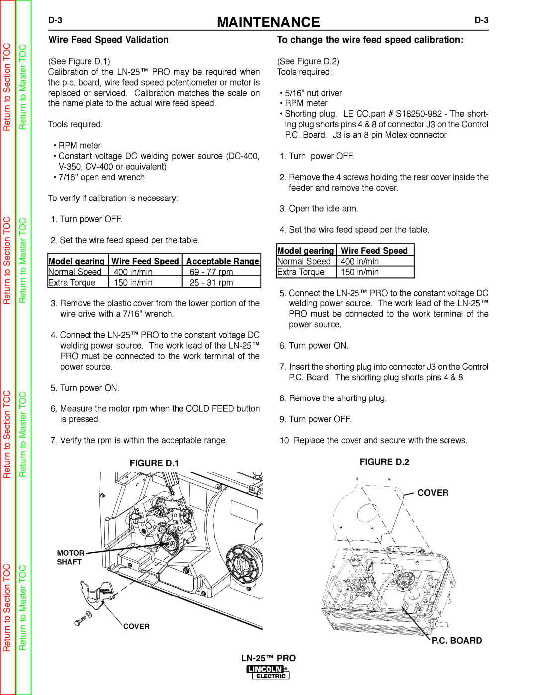
FIGURE D.1 | FIGURE D.2 |
 COVER
COVER
MOTOR ![]()
![]()
SHAFT
COVER