Appendix C Connecting to DC Power
Grounding the Switch
•
•Four leads of
•
Grounding the Switch
Warning This equipment is intended to be grounded. Ensure that the host is connected to earth ground during normal use. Statement 39
Warning When installing the unit, always make the ground connection first and disconnect it last. Statement 42
Caution To make sure that the equipment is reliably connected to earth ground, follow the grounding procedure instructions, and use a
Preparing the Ground Wire
Before you ground the switch to earth ground, you must prepare the ground wire. Follow these steps. Make sure to follow any grounding requirements at your site.
Step 1 Locate the ground lug and the two
Use a standard Phillips screwdriver or a ratcheting torque screwdriver with a Phillips head.
Set the screws and the ground lug aside.
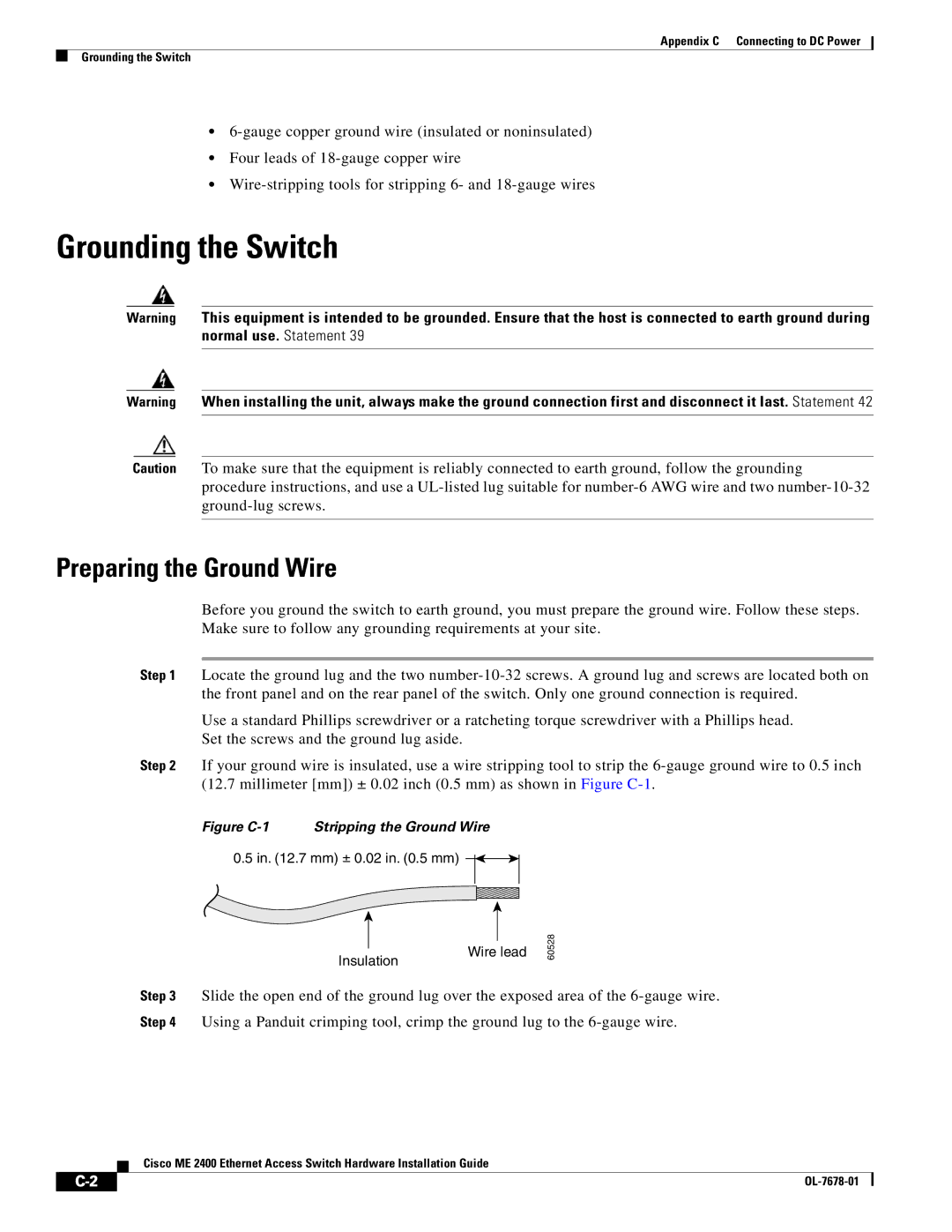
Step 2 If your ground wire is insulated, use a wire stripping tool to strip the
Figure C-1 Stripping the Ground Wire
0.5 in. (12.7 mm) ± 0.02 in. (0.5 mm)
Insulation
Wire lead
60528
Step 3 Slide the open end of the ground lug over the exposed area of the
Step 4 Using a Panduit crimping tool, crimp the ground lug to the
Cisco ME 2400 Ethernet Access Switch Hardware Installation Guide
|
|
| |
|
|