Appendix C Connecting to DC Power
Wiring the
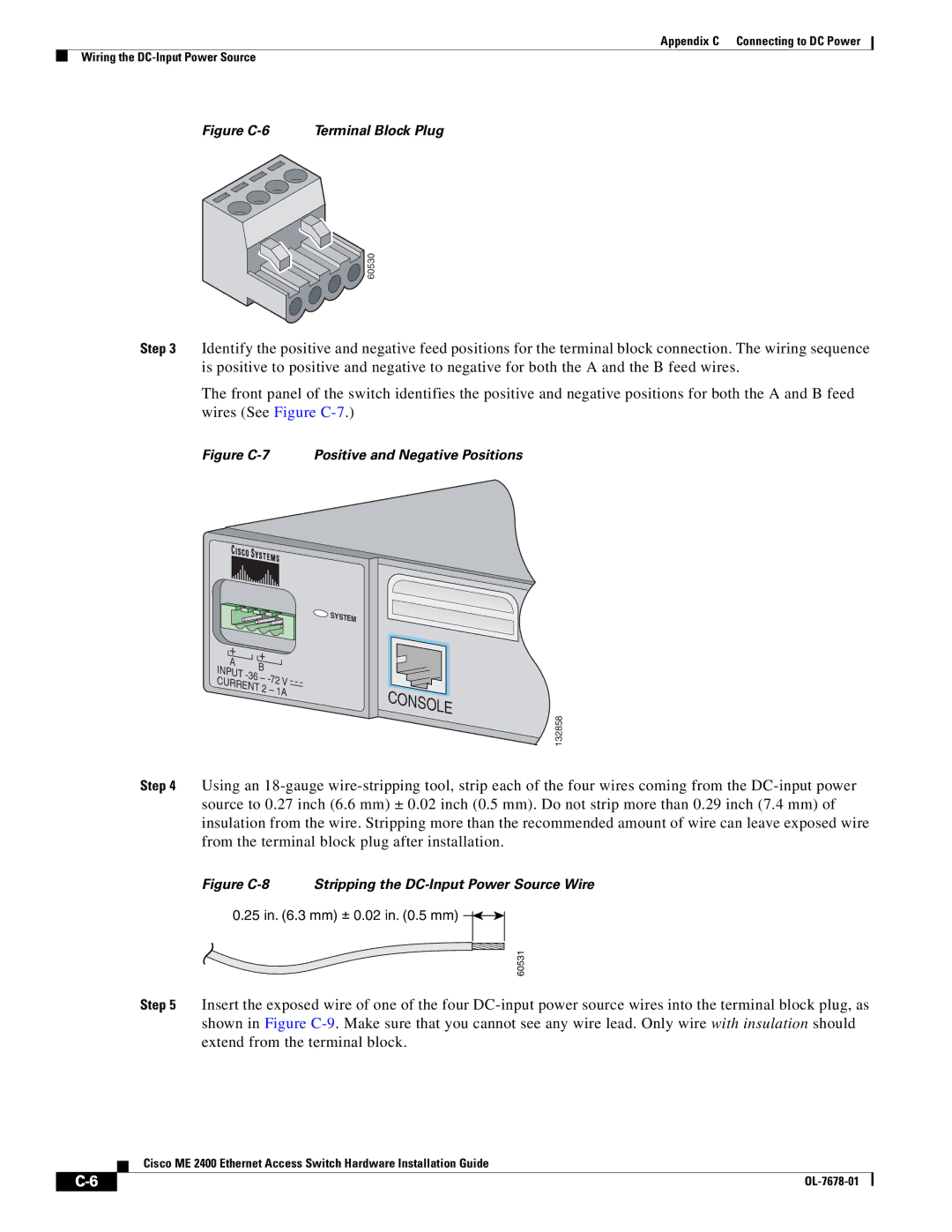
Figure C-6 Terminal Block Plug

![]() 60530
60530
Step 3 Identify the positive and negative feed positions for the terminal block connection. The wiring sequence is positive to positive and negative to negative for both the A and the B feed wires.
The front panel of the switch identifies the positive and negative positions for both the A and B feed wires (See Figure
Figure C-7 Positive and Negative Positions
![]() SYSTEM
SYSTEM
SYSTEM
+ | + |
| |
A |
| ||
B |
| ||
INPUT |
| ||
– | |||
| |||
CURRENT |
| ||
| 2 – 1A | ||
CONSOLE
132858
Step 4 Using an
Figure C-8 Stripping the DC-Input Power Source Wire
0.25 in. (6.3 mm) ± 0.02 in. (0.5 mm) ![]()
![]()
60531
Step 5 Insert the exposed wire of one of the four
Cisco ME 2400 Ethernet Access Switch Hardware Installation Guide
|
|
| |
|
|