Appendix B Connector and Cable Specifications
Cable and Adapter Specifications
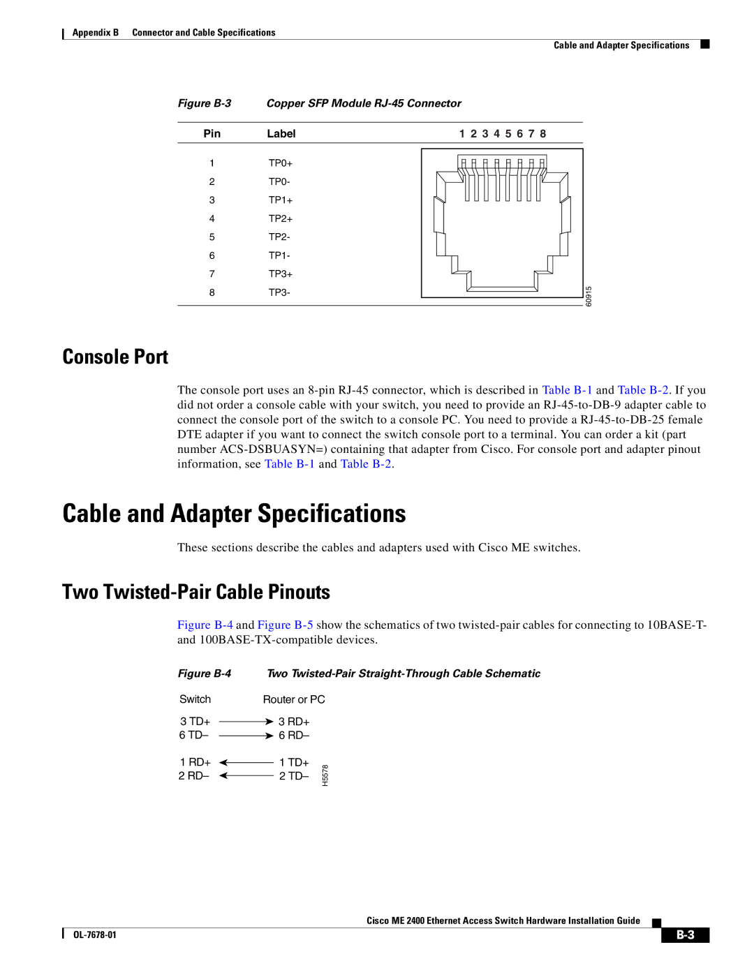
Figure B-3
Pin
1
2
3
4
5
6
7
8
Copper SFP Module | ||
Label | 1 2 3 4 5 6 7 8 | |
TP0+ |
| |
TP0- |
| |
TP1+ |
| |
TP2+ |
| |
TP2- |
| |
TP1- |
| |
TP3+ | 60915 | |
TP3- | ||
| ||
Console Port
The console port uses an
Cable and Adapter Specifications
These sections describe the cables and adapters used with Cisco ME switches.
Two Twisted-Pair Cable Pinouts
Figure B-4 and Figure B-5 show the schematics of two twisted-pair cables for connecting to 10BASE-T- and 100BASE-TX-compatible devices.
Figure B-4
Switch
3TD+
6 TD–
1RD+
2 RD–
Two Twisted-Pair Straight-Through Cable Schematic
Router or PC
 3 RD+
3 RD+  6 RD–
6 RD–
1 TD+ | H5578 | |
2 TD– | ||
|
Cisco ME 2400 Ethernet Access Switch Hardware Installation Guide
| ||
|