Appendix B Connector and Cable Specifications
Cable and Adapter Specifications
Crossover Cable and Adapter Pinouts
This section describes how to identify a crossover cable and also describes the adapter pinouts.
Identifying a Crossover Cable
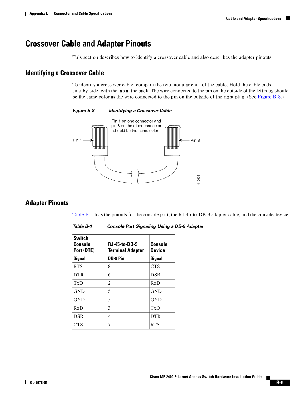
To identify a crossover cable, compare the two modular ends of the cable. Hold the cable ends
Figure B-8 Identifying a Crossover Cable
Pin 1 on one connector and pin 8 on the other connector should be the same color.
Pin 1 |
|
|
|
|
| Pin 8 |
|
| |||||
|
|
|
|
|
|
|
H10632
Adapter Pinouts
Table
Table
Switch |
|
|
Console | Console | |
Port (DTE) | Terminal Adapter | Device |
|
|
|
Signal | Signal | |
|
|
|
RTS | 8 | CTS |
|
|
|
DTR | 6 | DSR |
|
|
|
TxD | 2 | RxD |
|
|
|
GND | 5 | GND |
|
|
|
GND | 5 | GND |
|
|
|
RxD | 3 | TxD |
|
|
|
DSR | 4 | DTR |
|
|
|
CTS | 7 | RTS |
|
|
|
Cisco ME 2400 Ethernet Access Switch Hardware Installation Guide
| ||
|