Appendix C Connecting to DC Power
Wiring the
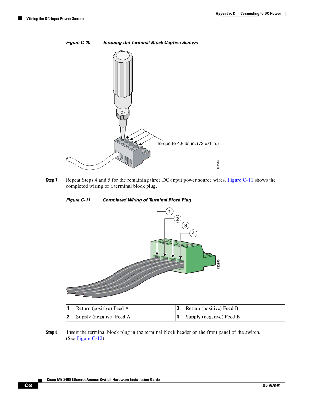
Figure C-10 Torquing the Terminal-Block Captive Screws
![]()
![]()
![]() Torque to 4.5
Torque to 4.5
60533
Step 7 Repeat Steps 4 and 5 for the remaining three
Figure C-11 Completed Wiring of Terminal Block Plug
1 |
2 |
3 |
4 |
132850
1 | Return (positive) Feed A | 3 | Return (positive) Feed B |
|
|
|
|
2 | Supply (negative) Feed A | 4 | Supply (negative) Feed B |
|
|
|
|
Step 8 Insert the terminal block plug in the terminal block header on the front panel of the switch. (See Figure
Cisco ME 2400 Ethernet Access Switch Hardware Installation Guide
|
|
| |
|
|