To turn on the DTR digital sensing in the modem, *DTRI should be set to 1. To turn on the RTS digital sensing, *RTSI should be set to 1. DTRI will respond to pin 4 on the serial port. RTSI will respond to pin 7.
Tip: To use only DTR or only RTS, you only need to configure the one you will be using.
To allow monitoring reports to be sent as a RAP message, enable *PPINPUTEVT by setting it to 1.
Connecting your device to the Serial Port
You can connect a standard RS232 serial cable to the PinPoint‐E serial port. If you want to use the DTR switch, wire in a Normally Open switch between the DTR, pin 4, and signal ground of pin 5, the external case, or the power ground. Refer to the figures below. If you want to use the RTS switch, use RTS, pin 7, to the ground. If you are using both DTR and RTS switches, you can use the same ground for both.
Caution: Never apply voltage to the DTR or RTS inputs. DTR and
RTS can only be switched open or closed to ground.
Tip: You may be able to purchase a customizable serial cable to use with DTR and RTS inputs. Contact your Sierra Wireless represen- tative for more information.
When the switch is closed and with *PPINPUTEVT configured, a RAP report will be sent to the destination IP address indicating that a contact closure has taken place (an external physical event has occurred). Refer to the GPS chapter for more information on the RAP protocol.
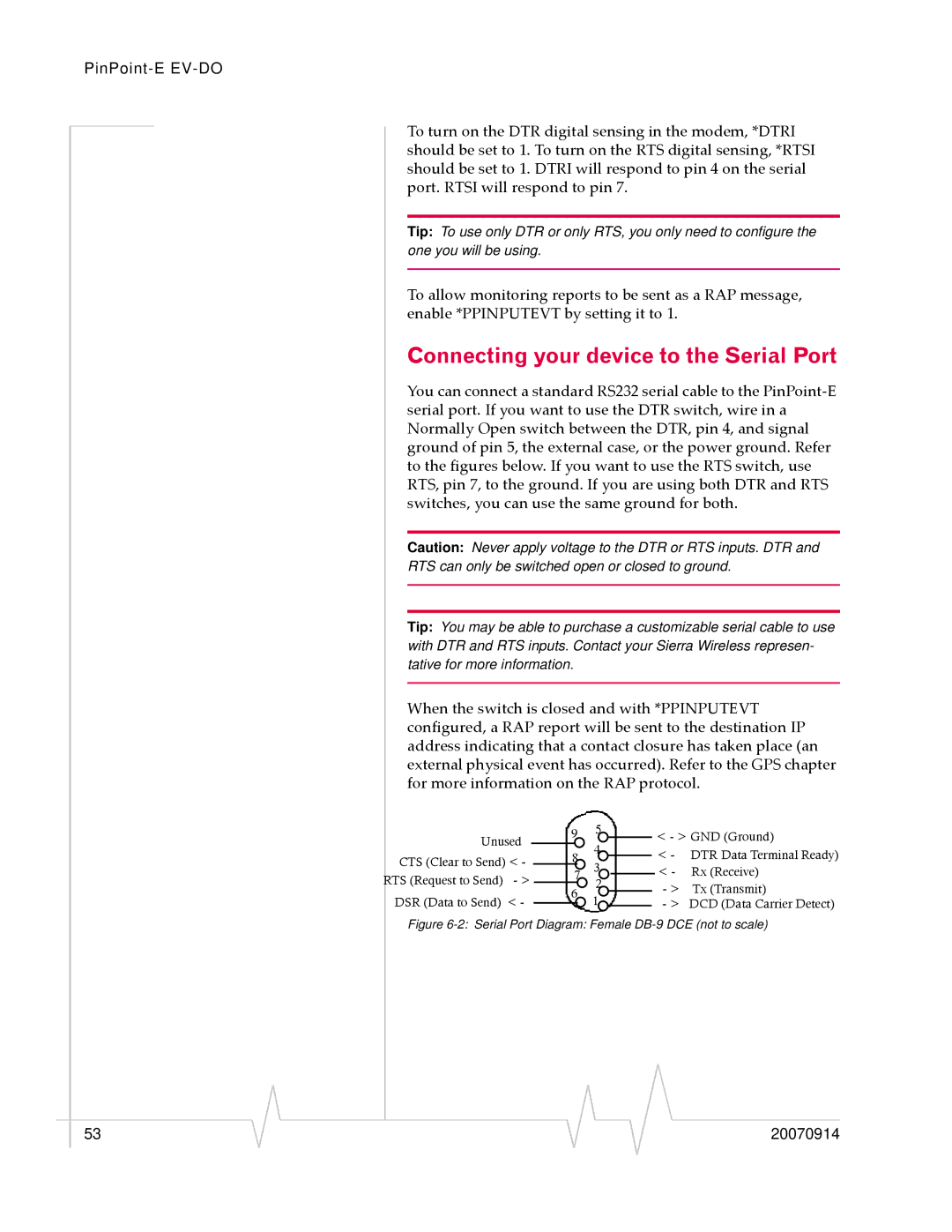
Unused CTS (Clear to Send) < - RTS (Request to Send) - > DSR (Data to Send) < -
9 |
| 5 |
|
|
| < - > GND (Ground) | ||
| 4 |
|
|
| ||||
|
|
|
|
|
| < - DTR Data Terminal Ready) | ||
| 8 |
|
|
| ||||
3 |
|
|
| |||||
|
|
|
|
|
| < - | Rx (Receive) | |
| 7 |
|
|
| ||||
2 |
|
| ||||||
| 6 |
|
|
| - > | Tx (Transmit) | ||
| 1 |
| ||||||
|
|
|
| - > DCD (Data Carrier Detect) | ||||
|
|
|
|
|
| |||
|
|
|
|
|
| |||
Figure 6-2: Serial Port Diagram: Female DB-9 DCE (not to scale)
|
|
|
|
|
|
|
53 |
|
|
|
|
| 20070914 |
|
|
|