|
|
|
|
|
|
|
|
|
|
|
|
| ElECTriCal DiaGrams |
|
|
|
|
|
|
|
|
|
|
|
|
|
|
|
|
|
|
|
|
|
|
|
|
|
|
|
| ||||||||||||||||||
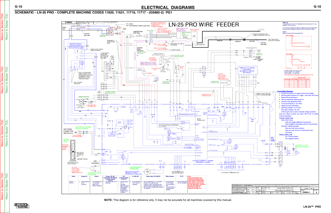
sChEmaTiC - |
|
|
|
|
|
|
|
|
|
|
|
|
|
|
|
|
|
|
|
|
|
|
|
|
|
|
|
|
|
|
|
|
|
|
|
| |||||||||||||||||||||||
|
| ENGINEERING CONTROLLED CHANGE DETAIL: RELEASED A.03 FROM "X". |
|
|
|
|
| When tach feed back is lost, |
|
|
|
|
|
|
|
|
|
|
|
|
|
|
|
|
| ||||||||||||||||||||||||||||||||||
WORK |
| 6 | 1 of 2 P17 | No |
|
|
| 21A |
|
| P7 = 16 PIN |
|
|
| (controlled by72 HZ TO 1.2 KHZ |
|
|
|
|
|
|
|
|
|
|
| If the feeder is | ||||||||||||||||||||||||||||||||
|
| MANUFACTURER: |
|
|
|
|
|
|
|
|
| the voltage to the motor is a |
|
|
|
|
|
|
|
|
|
|
|
|
|
|
|
|
|
|
|
|
|
|
|
|
|
|
|
|
|
|
|
|
| On | |||||||||||||
667C | 3 |
|
| 667A |
|
|
|
|
|
| P17 = 6 PIN (Both are located on lower front) | constant 10VDC. |
|
|
|
|
|
|
|
|
|
|
|
|
|
|
|
|
|
|
|
|
|
|
|
|
|
|
|
|
|
|
|
|
|
| polarity LED |
|
|
| |||||||||
|
|
|
|
|
|
|
|
|
|
| software) |
|
|
|
|
|
|
|
|
|
|
|
|
|
|
|
|
|
|
|
|
|
|
|
|
|
|
|
|
|
|
|
|
|
|
|
|
|
|
| |||||||||
CLIP |
|
|
|
| 621A |
|
|
| + | P17 | 4 | 667B |
|
|
|
|
|
|
|
|
| Motor case is at |
|
| Motor resistance |
|
|
|
|
|
|
|
|
|
|
|
|
|
|
|
|
|
|
|
|
|
| not start until the trigger is released and then depressed again. | |||||||||||
|
|
|
|
|
| 21B |
|
| 2 of 2 |
|
|
|
|
| Top of motor |
|
|
|
|
|
|
|
|
|
|
|
|
|
|
|
|
|
|
|
|
|
|
|
|
|
|
|
|
|
|
|
|
| |||||||||||
|
|
|
|
|
|
|
| D1 |
|
| 21C |
| Leads Pass through |
| electrode potential |
| is 1.5 ohms |
|
|
|
|
|
|
|
|
|
|
|
|
|
|
|
|
|
|
|
|
|
| Notes: |
|
|
|
| |||||||||||||||
|
|
|
|
|
|
|
|
|
| 1 |
|
|
| 1 |
| (METER DEPENDENT) |
|
|
| Motor is located |
|
|
|
|
|
|
|
|
|
|
|
|
|
|
|
|
|
|
|
|
|
|
|
|
|
|
|
| |||||||||||
|
|
| case front |
|
|
|
| 67B |
|
| toroid2times. |
|
| 2 |
|
|
|
|
| R |
|
|
|
|
|
|
|
|
|
|
|
|
|
|
|
|
|
|
|
|
|
|
|
|
|
| Motor overcurrent limit varies with WFS. |
| |||||||||||
|
|
|
|
| - |
|
|
| 531 |
|
|
|
|
|
|
|
|
| behind |
|
|
|
|
|
|
|
|
|
|
|
|
|
|
|
|
|
| PLASTIC HOUSED BOLTED |
|
|
|
|
| ||||||||||||||||
|
|
| strain relief | Located on |
|
|
|
| L4 |
| 531 | 3 |
|
|
|
|
| U |
|
| glastic panel |
|
|
|
|
|
|
|
|
|
|
|
|
|
|
|
|
|
|
|
|
|
|
|
|
|
|
| |||||||||||
667D |
|
|
|
|
|
| 537 |
|
|
|
|
|
|
|
|
|
| FEED |
|
|
|
|
|
|
|
|
|
|
|
|
|
|
| CONNECTION (BASE CENTER) |
|
|
|
|
| Before |
|
|
|
| |||||||||||||||
|
|
|
|
| Case front |
|
|
|
|
|
| 537 | 4 |
|
|
|
|
| B |
|
| MOTOR / |
|
| PLATE |
|
| 67C |
|
|
|
|
|
|
|
|
|
|
|
|
|
|
|
|
|
|
|
| Current |
|
|
|
| ||||||
|
|
|
|
|
|
|
|
|
|
|
|
| 534 |
|
| 534 | 5 |
|
|
|
|
|
|
|
| GEARBOX |
|
|
|
|
| 67D |
|
|
|
|
|
|
|
|
|
|
|
|
|
| From Power Source |
| Level |
|
|
|
| ||||||
|
|
|
|
|
|
|
| IN HARNESS |
|
|
|
|
| 551 | 6 |
|
|
|
|
| B |
|
|
|
|
|
|
|
|
|
| copper bar |
|
|
|
|
|
|
|
|
|
|
|
|
|
|
|
|
|
| |||||||||
|
|
|
|
|
|
|
|
|
|
|
|
| 7 |
|
|
|
|
|
|
|
|
|
|
|
|
|
|
|
|
|
|
| copper bar |
| weld cable |
|
| (Electrode Connection) |
| 4.5 |
|
|
|
| |||||||||||||||
|
|
|
|
|
|
|
| CENTER BASE |
|
|
|
| 550 | 8 |
|
|
|
|
| W |
|
|
|
|
|
|
|
|
|
|
|
|
|
|
|
|
|
|
| case back |
|
|
|
|
| 3.5 |
|
|
|
| |||||||||
MOTOR FILTER P.C. |
|
|
|
| AREA |
|
|
| 67C |
|
| P9 |
|
|
|
|
|
| TAKEN WITH 40 V INPUT |
|
|
|
|
|
|
|
|
|
|
|
|
|
|
|
|
|
|
|
|
|
|
|
|
|
|
|
|
|
| ||||||||||
|
|
|
|
|
|
|
|
|
| L12081 2.6 V @ 50 IPM |
|
| 67C & 67D |
| gun connector |
|
|
|
|
|
|
|
|
|
|
|
|
|
|
| strain relief |
|
|
|
|
|
|
|
|
|
| ||||||||||||||||||
|
|
|
|
|
|
|
|
| 67B |
|
|
|
|
|
|
|
|
|
|
|
|
|
|
|
|
|
|
|
|
|
|
|
|
|
|
|
|
|
|
| |||||||||||||||||||
BOARD SCHEMATIC= | 667D |
|
|
|
|
|
|
|
|
|
|
| 27 V @ 700 IPM |
| IN CV MODE. |
|
|
|
|
|
|
|
|
|
|
|
|
|
|
|
|
|
|
|
|
|
|
|
|
|
|
|
|
|
| Preset |
| ||||||||||||
S27592 BEFORE 6/15/2009 |
|
|
|
|
|
|
|
|
|
|
|
|
|
|
|
|
|
|
|
|
|
|
|
|
|
|
|
|
|
|
|
|
|
|
|
|
|
|
|
|
|
|
|
|
|
|
|
|
|
|
|
|
| ||||||
|
|
|
|
|
|
|
|
|
| Leads Pass |
|
|
|
|
|
|
|
|
|
|
|
|
|
|
|
|
|
|
|
|
|
|
|
|
|
|
|
|
|
|
|
|
|
|
|
|
|
|
|
|
|
|
| WFS |
| ||||
S27505 AFTER 6/15/2009 |
| USED FOR FILTERING |
|
|
|
|
|
|
|
|
| L13084 2.6 V @ 25 IPM |
|
|
|
|
|
|
|
|
|
|
|
|
|
|
|
|
|
|
|
|
|
| TRIGGER CONNECTOR |
|
|
|
|
|
|
|
|
|
| ||||||||||||||
|
|
|
|
|
|
|
|
|
| through |
|
|
| 32 V @ 400 IPM |
| EXTRA TORQUE |
|
|
|
|
|
|
|
|
|
|
|
|
|
|
|
|
|
|
| J14 |
| TRIGGER |
|
|
|
|
|
|
|
|
|
|
| ||||||||||
|
|
|
|
| INVERTER NOISE |
|
|
|
|
|
|
| toroid2times. |
|
|
|
|
|
|
|
|
|
|
|
|
|
|
|
|
|
|
|
|
|
|
| 622A |
|
|
| A |
|
|
|
|
|
|
|
|
|
|
|
|
| |||||
|
|
|
|
|
|
|
|
|
|
|
|
|
|
|
|
|
|
|
|
|
|
|
|
|
|
|
|
|
|
|
|
|
|
|
|
|
|
|
|
|
|
| INPUT |
|
|
|
|
|
|
|
|
|
|
| |||||
|
|
|
|
|
| 14 PIN REMOTE |
|
|
|
| Located on Wire |
|
|
|
|
|
|
|
|
|
|
|
|
|
|
|
|
|
|
|
|
|
|
|
|
| 500A |
|
|
| B |
|
|
|
|
|
|
|
|
|
|
|
|
| |||||
|
|
|
|
|
|
|
|
|
| Drive Panel |
|
|
| TRIGGER INTERLOCK |
|
|
|
|
|
|
|
|
|
|
|
|
|
|
|
|
|
|
|
|
|
|
| C |
|
| Located on |
|
|
|
|
| After |
|
|
|
| ||||||||
|
|
|
|
|
|
|
|
|
|
|
|
|
|
|
|
|
|
|
|
|
|
|
|
|
|
|
|
|
|
|
|
| 555A |
|
|
|
|
|
|
|
|
|
|
|
|
|
| ||||||||||||
|
|
|
|
|
| LEADS ARE | NOT |
|
|
|
| L5 |
|
| (NOT PRESENT ON |
|
| S1, S2 & S3 Located |
|
|
|
|
|
|
|
|
|
|
|
|
|
|
|
|
| D |
|
| Case Front |
|
|
|
|
| Current |
|
|
|
| ||||||||||
|
|
|
|
| 667E | PRESENT BUT |
|
|
|
|
|
|
|
| S1 |
|
|
|
|
|
|
|
|
|
|
|
|
|
|
|
|
|
| 622B | E | 0V.=TRIGGER |
|
|
|
|
|
| Level |
|
|
|
| ||||||||||||
|
|
|
|
| NOT USED IN | USED |
|
|
|
|
| 15V=2 STEP |
|
| on Wire Drive Panel |
|
|
|
|
|
|
|
|
|
|
|
|
|
|
|
|
|
|
|
|
|
|
|
|
|
|
| |||||||||||||||||
|
|
|
|
|
| THIS UNIT. | J18 |
|
|
|
|
|
|
|
|
|
|
|
|
|
|
|
|
|
|
|
|
|
|
|
|
|
|
|
|
|
|
|
|
|
| CLOSED |
|
|
|
|
|
|
|
|
|
|
| ||||||
|
|
|
|
|
|
|
|
|
|
|
|
|
|
| 0V=TRIGGER |
| 509E |
|
|
|
|
|
|
|
|
|
|
|
|
|
|
|
|
|
|
|
|
|
|
|
| 15VDC.=TRIGGER |
|
|
|
|
| 4.5 |
|
|
|
| |||||||
|
|
|
|
|
|
|
|
|
|
|
|
|
|
|
|
| INTERLOCK |
|
|
| 587 |
|
|
|
|
|
|
|
|
|
|
|
|
|
|
|
|
|
|
|
|
|
|
|
|
| OPEN |
|
|
|
|
|
| 3.5 |
|
|
|
| |
|
|
|
|
| B2 |
|
|
|
|
|
|
| Trigger Interlock does not stop |
|
|
|
|
|
|
| 509B |
|
|
|
|
|
|
|
|
|
|
|
|
|
|
|
|
|
|
|
|
|
|
|
|
|
|
|
|
|
| ||||||||
|
|
|
|
|
| 9 |
|
|
|
|
|
|
|
|
|
|
|
|
|
|
|
|
|
|
|
|
|
|
|
|
|
|
|
|
|
|
|
|
|
|
|
|
|
|
|
|
|
|
| ||||||||||
|
|
|
|
|
|
|
|
|
|
|
|
| welding when the arc is broken. |
|
|
|
|
|
|
|
|
|
|
|
|
|
|
|
|
|
|
|
|
|
|
|
|
|
|
|
|
|
|
|
|
|
|
|
|
|
|
|
| ||||||
|
|
|
|
|
|
|
| 10 |
|
|
|
|
| Pull and release to end the weld. |
| 509E |
| 509D |
|
|
|
|
|
|
|
|
|
|
|
|
|
|
|
|
|
|
|
|
|
|
|
|
|
|
|
|
|
|
|
| Preset |
| |||||||
|
|
|
|
|
| B1 |
| 77C |
|
|
|
|
| S3 |
|
|
|
|
|
|
|
|
|
|
|
|
|
|
|
|
|
|
|
|
|
|
|
|
|
|
|
|
|
|
|
|
| WFS |
| ||||||||||
|
|
|
|
| 5 |
|
|
| 667B |
|
|
| 0V=COLD FEED |
|
| S2 | 15V=CV |
|
|
|
| 622 | 4 |
|
|
|
|
|
|
|
|
| TIMER KIT P.C. BOARD |
|
|
|
|
|
|
|
| *Extra Torque | 370 | 530 | 700 |
| |||||||||||||
|
|
|
|
|
|
|
| 4 | 76C |
|
|
| ANALOG |
|
|
| 530A | CC | 0V=CC |
|
|
|
| 2 |
|
|
|
|
|
|
| 509B |
|
|
|
|
|
|
|
| 180* | 257* | 400* |
| |||||||||||||||
|
|
|
|
|
|
|
| 3 | 75C |
|
|
|
| + |
|
| (N.O.) |
|
|
|
|
|
|
|
|
|
| 500 |
|
|
|
|
|
|
|
| (OPTIONAL) |
|
|
|
|
|
|
|
| The WFS range of the |
|
| |||||||||||
|
|
|
|
|
|
| J15 |
|
|
|
| VOLTMETER |
|
|
| COLD FEED |
|
|
|
|
|
|
|
|
|
|
|
|
|
|
|
|
|
|
|
| SCHEMATIC = M21341 |
|
|
|
|
|
|
|
|
| |||||||||||||
|
| USED TO DISCHARGE |
| 1 |
|
|
|
|
|
|
|
|
|
|
| CV |
|
|
|
|
|
| 555 |
|
|
|
|
|
|
|
|
|
|
|
|
|
|
|
|
| Normal Speed = 40- 700 IPM. |
|
|
| |||||||||||||||
|
|
|
| 6 |
| 21E |
|
|
| - | 40V MAX. |
|
|
|
|
|
|
|
|
|
|
| 3 |
|
| 4 O COIL |
|
|
|
|
|
| SEE PAGE 2 |
|
|
|
|
|
|
|
| Extra Torque = 25- 400 IPM. |
|
|
| ||||||||||||||
|
| POWER SUPPLY CAP |
|
|
|
|
|
|
|
|
|
|
|
|
|
| 509C |
|
|
|
|
|
|
|
|
|
|
|
|
|
|
|
|
|
|
|
|
|
|
|
|
|
|
| |||||||||||||||
|
| AFTER A HIGH VOLTAGE |
|
| 2 |
|
|
|
|
|
|
|
|
| 721 |
|
|
|
|
| 523 |
|
|
|
|
|
| 1 of 4 |
|
| 0 VDC OPEN |
|
|
|
|
|
|
|
|
|
|
|
|
|
|
|
| WFS limited by arc voltage when operating across the arc | |||||||||||
|
| TRANSIENT. LATER |
|
| 7 |
|
|
|
|
|
|
|
|
|
|
|
|
|
|
|
|
|
|
|
|
|
|
| 3 VDC CLOSED |
|
|
|
| 607 608 606A 605 4B |
| 509B 601 |
|
|
|
|
|
|
|
|
|
|
| ||||||||||||
|
| RELOCATED TO THE |
|
| 8 |
|
|
|
|
|
|
|
|
|
|
|
|
|
|
|
|
|
|
|
|
|
|
| P7 |
|
| 12 VDC COIL |
|
|
|
|
|
|
|
|
|
|
|
| Maximum WFS |
| |||||||||||||
621 |
| CONTROL BOARD. |
|
|
|
|
|
|
|
|
|
|
|
|
|
| P16 |
|
|
|
|
|
|
|
|
|
|
|
|
| PWM CONTROLLED |
|
|
|
|
|
|
|
|
|
|
|
|
|
|
|
| Feeder Input Volts | Standard Gear | Extra Torque |
| ||||||||
|
|
|
|
|
|
|
|
|
|
|
|
|
|
|
|
|
|
| 4 | 2 | 3 | 1 |
|
|
|
|
|
|
|
|
|
|
|
|
|
|
|
|
|
|
|
|
|
|
|
|
|
| |||||||||||
|
|
|
|
|
|
|
|
|
|
|
|
|
|
|
|
|
| 3 of 4 |
|
|
|
|
|
|
|
|
|
| Located under |
|
|
|
|
|
|
|
|
|
|
|
|
|
|
|
|
|
|
| 15 | 280 |
| 210 |
| ||||||
| NOT PRESENT |
|
|
|
|
|
|
|
|
|
|
|
|
|
|
| Located on |
|
|
|
|
|
|
|
|
|
| CONTACTOR |
|
|
|
| 8 | 7 6 5 | 4 | 3 | 2 | 1 |
|
|
|
|
|
|
| 17 | 340 |
| 235 |
| |||||||||
|
|
|
|
|
|
|
|
|
|
|
|
|
|
|
|
| top of motor |
|
|
|
|
|
|
|
|
|
| Wire Drive Panel |
|
|
|
| P60 |
|
|
|
|
|
|
|
| ||||||||||||||||||
| ON S27505 |
|
|
| 10 | 75C |
|
|
|
|
|
|
|
|
|
|
|
|
|
|
|
|
|
|
|
|
|
|
|
|
|
|
|
|
|
|
|
|
|
|
|
|
|
|
|
|
|
| 21 | 440 |
| 400 |
| ||||||
|
|
|
|
|
|
|
|
|
|
|
|
|
|
|
|
|
|
|
|
|
|
|
|
|
|
|
|
|
|
|
|
|
|
|
|
|
|
|
|
|
|
|
|
|
|
|
|
|
|
|
|
| 24 | 520 |
| 400 |
| ||
|
|
|
|
|
|
| 11 | 76C |
|
|
|
|
|
|
|
|
|
|
|
|
|
|
|
|
|
|
|
|
|
|
|
|
|
|
|
|
|
|
|
|
|
|
|
|
|
|
|
|
|
|
|
|
|
|
|
| |||
|
|
|
|
|
|
|
|
|
|
|
|
|
|
|
|
|
|
|
|
|
|
|
|
|
|
|
|
|
|
|
|
|
|
|
|
|
|
|
|
|
|
|
|
|
|
|
|
|
|
|
|
| 27 | 600 |
| 400 |
| ||
|
|
|
|
|
|
| 12 | 77C |
|
|
|
|
|
|
|
|
|
|
|
|
|
|
|
|
|
|
|
|
|
|
|
|
|
|
|
|
|
|
|
|
|
|
|
|
|
|
|
|
|
|
|
|
|
|
|
|
|
|
|
|
|
|
|
|
| P7 |
| Connector located |
|
|
|
|
|
|
|
|
|
|
|
|
|
|
|
|
|
|
|
|
|
|
|
|
|
|
|
|
|
|
|
|
|
|
|
|
|
|
|
|
|
| Control Board Summary |
|
|
|
| ||||
|
|
|
|
|
| 4 of 4 |
| behind case front |
|
|
|
|
|
|
|
|
|
|
|
|
|
|
|
|
|
|
|
|
|
|
|
|
|
|
|
|
|
|
|
|
|
|
|
|
| JUMPER TOGETHER FOR |
|
|
|
| Converts arc power to a usable control circuit voltage. | ||||||||
|
|
|
|
|
|
|
|
|
|
|
|
|
|
|
|
|
|
|
|
|
|
|
|
|
|
|
|
| ISOLATED |
|
|
|
|
|
|
|
|
|
|
|
|
|
|
|
|
|
| ||||||||||||
|
|
|
|
|
| 575A | 6 | 575A |
|
|
|
|
|
|
|
|
|
|
|
|
|
|
|
|
|
|
|
|
|
|
|
|
|
|
|
|
|
|
|
|
|
|
|
|
| EXTRA TORQUE MACHINE |
|
|
| Receives switch signals from Trigger, Cold Feed, Gas Purge | |||||||||
|
| LocatedonCaseFront |
|
|
|
|
|
|
|
|
|
|
|
|
|
|
|
|
|
|
|
|
|
|
| POWER SOURCE |
|
|
|
|
|
|
|
|
|
|
|
|
|
|
|
|
| ||||||||||||||||
|
| 576A | 7 | 576A |
|
|
|
|
|
|
|
|
|
|
|
|
|
|
|
|
|
|
|
|
|
|
|
|
|
|
|
|
|
|
|
|
|
|
|
|
|
|
|
|
|
|
|
|
| Reads WFS potentiometer. |
|
|
| ||||||
| 10K/2W |
| 575A | 577A | 8 | 577A |
|
|
|
|
|
| 534 | 550 |
| 21D |
|
|
|
|
|
|
|
|
|
|
|
|
|
|
| 4 |
|
|
|
|
|
|
|
|
|
|
|
|
|
|
|
|
|
|
| Communicates with optional timer kit. |
| ||||||
| R1 |
|
|
|
|
|
|
| 537 | 67F |
|
|
| 530 |
|
|
|
| 622 |
|
|
|
|
|
|
|
|
|
| 607 | 608 | 606 | 605 |
| 601 | EXTRA |
|
|
|
|
|
| |||||||||||||||||
|
|
|
| 576A |
|
|
|
|
|
|
|
| 551 | 721 |
|
|
|
|
|
|
|
|
|
|
|
|
|
|
|
|
|
|
|
|
|
|
|
| Controls motor speed with PWM. |
|
| ||||||||||||||||||
|
|
|
|
| 577A |
|
|
|
|
|
|
|
| 531 |
|
|
|
|
|
|
|
|
|
|
|
|
|
|
|
|
|
| 2 |
|
| 578 | 507 |
|
|
|
|
|
|
|
|
|
|
|
|
|
|
|
|
|
|
|
|
| |
|
|
|
|
|
|
|
|
|
|
|
|
|
|
|
|
|
|
|
|
|
| 587 | 523 | 509A |
|
|
| 500 |
|
|
|
|
|
| 555 |
|
|
|
|
|
|
|
|
| TORQUE |
|
|
|
| Turns Gas Solenoid on, off, PWM. |
|
| |||||||
| WIRE FEED SPEED |
| 0 VDC MIN. WFS |
|
|
|
|
|
|
|
|
|
|
|
|
|
|
|
|
|
|
|
|
|
|
|
|
|
|
|
|
|
|
|
|
|
|
|
|
|
|
|
|
|
|
|
|
|
| ||||||||||
|
|
|
|
|
|
|
|
|
|
|
|
|
|
|
|
|
|
|
|
|
|
|
|
|
|
|
|
|
|
|
|
|
|
|
|
|
|
|
|
|
|
|
|
|
|
|
|
| Reads the motor tachometer. |
|
|
| |||||||
|
| CONTROL |
|
|
|
|
|
| MOTOR |
|
|
|
|
|
|
|
|
|
|
|
|
|
|
|
|
|
|
|
|
|
| +35V |
|
|
|
|
|
|
|
|
|
|
|
|
|
|
|
|
|
|
|
| |||||||
|
|
| 5 VDC MAX. WFS |
|
|
|
|
|
|
|
|
|
|
|
| +15V |
|
|
|
|
|
|
| Operating Voltage= |
|
| |||||||||||||||||||||||||||||||||
| POTENTIOMETER |
|
|
|
|
|
|
|
| SUPPLY |
|
|
|
|
|
|
|
|
|
|
|
|
|
|
|
|
| ||||||||||||||||||||||||||||||||
|
|
|
|
| 667 |
|
|
|
|
| 100K | +5V |
|
|
|
|
|
|
|
|
|
| +15V | +15V |
|
|
|
|
|
|
| 20 |
|
|
|
|
|
|
|
|
|
|
|
|
|
|
|
|
| Shut down Voltage= 130 VDC. |
|
|
| ||||||
|
|
|
|
|
|
|
|
|
| ohm | 10K |
|
|
|
|
|
|
|
|
|
|
|
|
|
|
|
|
|
|
| MOV |
|
|
|
|
|
|
|
|
|
|
|
|
|
|
|
|
|
|
|
|
| |||||||
|
|
|
|
|
|
|
|
|
| COM |
|
|
|
|
|
|
|
|
|
|
|
|
|
|
|
|
|
|
| TRIGGER | MACHINE |
| ohm |
|
|
|
|
|
|
|
|
|
|
|
|
|
|
|
|
| Thermal light turns on when shutdown voltage exceeded. | ||||||||
|
|
|
|
| B1 |
|
| B1 |
|
|
|
| ohm |
|
|
|
|
|
|
|
|
|
|
|
|
|
|
|
|
|
|
|
|
|
|
|
| +5V |
|
|
|
|
|
|
|
|
|
| |||||||||||
|
|
|
|
|
|
|
|
|
|
|
| +15V |
|
|
|
|
|
|
|
|
|
| TRIGGER INTERLOCK / 2 STEP | CC/VV | OUTPUT |
|
|
|
|
|
|
|
|
|
|
|
|
|
|
|
|
|
|
| Code and Serial numbers are below Wire Drive on plastic | ||||||||||||||
|
|
|
| B2 |
|
|
|
|
|
|
|
|
|
|
|
|
|
|
|
|
| ENABLE | CONTACTOR DRIVE |
|
|
|
|
|
|
|
|
|
|
|
|
|
|
|
|
|
| ||||||||||||||||||
|
|
|
|
|
|
| B2 |
|
|
|
|
|
| COM | .05 uF |
|
|
|
|
|
|
|
|
|
|
|
| COLD FEED |
|
|
|
|
|
|
|
|
|
|
|
|
|
|
|
|
|
|
|
|
| housing Nameplate. |
|
|
|
| |||||
|
|
| C1 |
|
|
|
|
|
|
|
|
|
|
| 600 V |
|
|
|
|
|
|
|
|
|
|
|
|
|
|
|
|
|
|
|
|
|
|
|
|
|
|
|
|
|
|
|
|
|
| Thermal “Yellow” Light |
|
|
|
| |||||
| C2 |
|
|
|
|
|
|
|
|
|
|
|
|
|
|
|
|
|
|
|
|
|
|
|
|
|
|
|
| MICRO |
|
|
|
|
|
|
|
|
|
|
|
|
| 100K |
|
|
|
|
|
|
|
|
|
| |||||
|
|
|
|
|
|
|
|
|
|
|
| +15V SPI |
|
|
|
|
|
|
|
|
|
|
|
|
|
|
|
|
| CONTROLLER |
|
|
|
|
|
|
|
|
|
|
|
|
|
|
|
|
|
|
| Motor Over Current |
|
|
|
| |||||
|
|
|
|
|
|
|
|
|
|
| POWER | +5V SPI |
|
|
|
|
|
|
|
|
|
|
|
| METER |
|
|
|
|
|
|
| COM |
|
|
|
|
|
|
|
| ohm |
|
|
|
|
|
|
|
| Motor and trigger disabled for 30 seconds. | ||||||||
|
|
|
|
|
|
|
|
|
|
|
|
|
|
|
|
|
|
|
|
|
|
| COMPENSATION |
|
|
|
|
|
|
|
|
|
|
|
|
|
|
|
|
|
|
|
|
|
|
|
|
|
| ||||||||||
|
|
| 621 |
|
|
|
|
|
| SUPPLY | +15V ISO |
|
|
|
|
|
|
|
|
|
|
|
|
|
| POLARITY |
|
|
|
|
|
|
|
|
|
|
|
|
|
|
|
|
|
|
|
|
|
|
| Must retrigger to start welding after 30 seconds pass. | |||||||||
|
|
|
|
|
|
|
|
|
|
|
|
|
|
|
| 721 IS DRIVEN NEGATIVE TO COMPENSATE |
| CIRCUIT |
|
|
|
|
|
|
|
|
|
|
|
|
|
|
|
|
|
|
|
|
|
|
| 4B |
|
| |||||||||||||||
|
|
|
|
|
|
|
|
|
|
|
| LED | +5VDC |
|
|
|
|
|
|
|
|
|
|
| SENSE |
|
|
|
|
|
|
|
|
|
|
|
|
|
|
|
|
|
|
|
|
|
| ||||||||||||
|
|
|
|
|
|
|
|
|
|
|
|
|
|
|
|
|
| FOR THE METER FOR DIODE DROP ERROR |
|
|
|
|
|
|
|
|
|
|
|
|
|
|
|
|
|
|
|
|
|
|
|
|
|
|
|
|
| Shutdown Voltage exceeded |
|
|
| ||||||||
| (LOCATED AT OUTSIDE |
|
|
|
|
|
| ISO | 35VDC |
|
|
|
|
| ON THE BRIDGE |
|
|
|
|
| +15 |
|
|
|
|
| GAS |
|
|
|
|
|
|
|
|
|
|
|
|
|
|
|
|
|
|
|
|
|
|
|
| ||||||||
GAS PURGE | REAR OF FEEDER) | C1 |
|
|
|
|
|
|
|
|
|
|
|
|
| MOTOR |
|
|
|
|
|
|
|
|
|
| ON - OFF |
|
|
|
|
|
|
|
|
|
|
|
|
|
|
|
|
|
|
|
|
|
| May occur with some inverters. |
| ||||||||
|
|
|
|
|
|
|
|
|
|
|
|
| SUPPLY |
|
|
|
|
|
|
|
|
|
| 0V = OFF |
|
|
|
|
|
|
|
|
|
|
|
|
|
|
|
|
|
|
|
|
| May occur with some CC machines with high | |||||||||||||
PUSHBUTTON |
|
|
| 610 |
|
|
|
|
|
|
|
|
|
|
|
|
|
|
|
|
|
|
|
|
|
|
|
|
|
|
|
|
|
|
|
|
|
|
|
|
|
|
|
|
|
|
|
|
|
|
| ||||||||
S4 |
|
|
|
|
| OVER |
| POWER |
|
|
|
|
|
|
|
|
|
| DRIVE |
|
|
|
|
|
|
|
| BURNBACK | 20msec |
|
|
|
|
|
|
|
|
|
|
|
|
|
|
|
|
|
|
| inductance. |
|
|
|
| ||||||
SWITCH (N.O.) |
|
| 612 |
|
|
|
|
|
|
|
|
|
|
|
|
|
|
|
|
|
|
|
|
|
|
|
|
|
|
|
|
|
|
|
|
|
|
|
|
|
|
|
|
|
|
|
|
|
|
|
| ||||||||
|
|
|
|
|
|
|
|
|
|
|
|
|
|
|
|
|
|
|
|
|
|
|
|
|
|
|
|
|
|
|
|
|
|
|
|
|
|
|
|
|
|
|
|
|
|
|
|
|
|
|
|
|
|
|
|
|
|
| |
13.5 VDC WHEN |
|
| C2 |
|
| VOLTAGE |
| SUPPLY |
|
|
|
|
|
|
|
|
|
| PWM |
|
|
|
|
|
|
| DRIVE |
|
|
|
|
|
|
|
|
|
|
|
|
|
|
|
|
|
|
|
|
| Polarity “Green” Light |
|
|
|
| ||||||
|
|
|
| PROTECTION |
|
|
|
|
|
|
|
|
|
|
|
|
|
|
|
|
|
|
|
|
|
|
|
|
|
|
|
|
|
|
|
|
|
|
|
|
|
|
|
|
|
|
| On= Positive Polarity |
|
|
| ||||||||
NOT DEPRESSED |
|
|
|
|
|
|
|
|
|
|
|
|
|
|
|
|
|
|
|
| MOTOR |
|
|
|
|
| BRAKE |
|
|
|
|
|
|
|
|
|
|
|
|
|
|
|
|
|
| GAS |
|
|
|
|
|
|
| ||||||
|
|
|
|
|
|
|
|
|
|
|
|
|
|
|
|
|
|
|
|
|
|
| BRAKE |
|
|
|
|
|
|
|
|
|
|
|
|
|
|
|
|
|
|
|
|
|
|
|
|
|
|
| Off= Negative Polarity |
|
|
| |||||
(OUTSIDE |
|
|
|
|
|
|
|
|
|
|
|
|
|
|
|
|
|
|
|
|
|
| DRIVE |
|
|
|
|
| MOTOR VOLTAGE | YELLOW THERMAL LED |
|
|
|
|
|
|
|
|
|
|
|
|
|
| FLOW |
|
|
|
|
|
| ||||||||
|
|
|
|
|
|
|
|
|
|
|
|
|
|
|
|
|
|
|
|
|
|
| CIRCUIT |
|
|
|
|
| MOTOR CURRENT |
|
|
|
|
|
|
|
|
|
|
|
|
|
|
|
|
|
|
|
|
|
| ||||||||
BACK OF |
|
|
|
|
|
|
|
|
|
|
|
|
|
|
|
|
| 0.05K |
|
| COM |
|
|
|
|
|
|
|
|
|
|
|
|
|
|
|
|
|
|
|
|
|
|
|
|
| +5V SPI | ENABLE |
|
|
|
|
|
|
| ||||
CASE) |
|
|
|
|
|
|
|
|
|
|
|
|
|
|
|
|
|
|
|
|
|
|
|
|
|
|
|
|
|
|
|
|
|
|
|
|
|
|
|
|
|
|
|
|
|
|
|
|
|
|
| 15 |
|
|
|
|
|
| |
|
|
|
|
|
|
|
|
|
|
|
|
|
|
|
|
|
| ohm |
|
|
|
|
|
|
|
|
|
|
|
|
|
|
|
|
|
|
|
|
|
|
|
|
|
|
|
|
|
|
|
|
|
|
|
|
|
|
|
| |
25 TO 35 |
|
|
|
|
|
|
|
|
|
|
|
|
|
|
|
|
|
|
|
|
|
|
|
|
|
| TACH |
| POLARITY LED |
| COM |
|
|
|
|
|
|
|
|
|
|
|
| B |
|
| 2B |
|
| (LOCATED AT TOP |
| ||||||||
|
|
|
|
|
|
|
|
|
|
|
|
|
|
|
|
|
|
|
|
|
|
|
|
|
| FREQUENCY = SPEED | FEEDBACK |
|
|
|
|
|
|
|
|
|
|
|
|
|
|
|
|
|
|
|
|
| 13 |
|
| ||||||||
NORMAL |
|
|
|
|
|
|
|
|
|
|
|
|
|
|
|
|
|
|
|
|
|
|
|
|
| 0V = MIN SPEED |
| WIRE FEED |
|
|
|
|
|
|
|
|
|
|
|
|
|
|
|
|
|
|
|
|
| 1B |
|
| FRONT OF FEEDER) |
| |||||
FLOW |
|
|
|
|
|
|
|
|
|
|
|
|
|
|
|
|
|
|
|
|
|
|
| 5V = MAX SPEED |
| SPEED |
|
|
|
|
|
|
|
|
|
|
|
|
|
|
|
|
|
|
|
|
|
|
|
|
|
|
|
| |||||
RATE |
|
|
|
|
|
|
|
|
|
|
|
|
|
|
|
|
|
|
|
|
|
|
|
|
|
|
|
| GAS PURGE |
| ARC ESTABLISHED |
|
| COM |
|
|
|
|
|
|
|
|
|
|
|
|
|
|
|
|
| YELLOW |
|
|
|
| |||
|
|
|
|
|
|
|
| +15V | COM |
|
| +35V |
|
|
|
|
|
|
|
|
|
|
|
|
|
|
|
|
|
|
|
|
|
|
|
|
|
|
|
|
|
|
|
|
|
|
|
| 14 | GREEN |
|
|
| ||||||
|
| BALL FLOAT |
|
|
|
|
|
|
|
|
|
|
|
|
|
|
|
|
|
|
|
|
|
|
|
| GAS SOLENOID |
|
|
|
|
|
|
|
|
|
|
|
|
|
|
|
| 1W |
|
| MOTOR |
|
|
| |||||||||
|
|
|
| 610 |
|
|
|
|
|
|
|
|
|
|
|
|
|
|
|
|
|
|
|
|
|
|
|
|
|
|
|
|
|
|
|
|
|
|
|
|
|
|
|
| 16 |
| THERMAL | POLARITY |
|
|
| ||||||||
|
| USE MIDDLE |
|
|
|
|
|
|
|
|
|
|
|
|
|
|
|
|
|
|
|
|
|
|
|
|
|
|
|
|
|
|
|
|
|
|
|
|
|
|
|
|
|
|
|
|
|
|
|
|
|
| |||||||
|
| OF BALL TO |
|
| 612 |
|
|
|
|
|
|
|
|
|
|
|
|
|
|
|
|
|
|
|
|
|
| PROGRAM |
|
|
|
|
|
|
|
|
|
|
|
|
|
|
|
|
| 2W |
|
|
|
| LED | LED |
|
|
| ||||
|
| SET |
|
|
|
|
|
|
|
|
|
|
|
|
|
|
|
|
|
|
|
|
|
|
|
|
|
|
|
|
|
|
|
|
|
|
|
|
|
|
|
|
|
|
|
|
|
|
| 708 | 9 |
|
|
|
|
|
| ||
|
|
|
|
|
|
|
|
|
|
|
|
|
|
|
|
|
|
|
|
|
|
|
|
|
|
|
|
|
|
|
|
|
|
|
|
|
|
|
|
|
|
|
|
|
|
|
|
|
|
|
|
|
|
|
| ||||
|
| ADJUST VALVE |
|
|
|
|
|
|
|
|
|
|
|
|
|
|
|
|
|
|
|
|
|
|
|
|
|
|
|
|
|
|
|
|
|
|
|
|
|
|
|
|
|
|
|
|
|
|
|
|
| ||||||||
FLOW METER | GAS |
|
|
|
|
|
|
|
|
|
| +5V SPI |
|
|
|
|
|
|
|
|
|
| FLEXIBLE POWER P.C. BOARD |
|
|
|
|
|
|
|
|
|
|
|
|
|
|
|
|
| 5 |
|
|
|
|
|
| ||||||||||||
|
|
|
|
|
|
|
|
|
|
|
|
|
|
|
|
|
|
|
| +5V |
|
|
|
| MISO MOSI CS0 | CS1 CS2 | CS3 SCLK | +5V SPI | +15V |
|
|
|
|
| 707 |
|
|
|
|
|
| ||||||||||||||||||
|
|
|
|
|
|
|
|
|
|
|
|
|
|
|
|
|
|
|
|
|
|
|
|
|
|
|
|
|
|
|
|
|
|
|
|
|
| ||||||||||||||||||||||
GOOD FOR Ar, CO2, |
|
| SOLENOID |
|
|
| COM |
|
|
|
|
|
|
|
|
|
|
|
|
|
|
|
|
| SCHEMATIC = G4783 |
|
|
|
|
|
|
|
|
|
|
|
|
|
|
|
|
|
|
| |||||||||||||||
CO2/Ar BLENDS |
|
|
|
|
|
|
|
|
|
|
|
|
|
|
|
|
|
|
|
|
|
|
|
|
|
|
|
|
|
|
|
|
|
|
|
|
|
|
|
|
|
|
|
|
|
|
| 2 of 4 |
|
|
|
|
| ||||||
|
|
|
|
|
| 690 |
|
|
|
|
|
|
|
|
|
|
|
|
|
|
|
|
|
|
|
|
|
|
|
|
|
|
|
|
|
|
|
|
|
|
|
|
|
|
|
|
|
|
|
|
|
|
|
|
|
|
| ||
22 O COIL |
|
|
|
|
|
|
|
|
| (LOCATEDINSIDEOF |
|
|
|
|
|
|
|
|
|
|
|
|
|
|
|
|
|
|
|
|
|
|
| P7 |
|
|
|
|
|
| |||||||||||||||||||
|
|
|
|
|
|
|
|
|
|
|
|
|
|
|
|
|
|
|
|
|
|
|
|
|
|
|
|
|
|
|
|
|
|
|
|
|
|
| |||||||||||||||||||||
0 VDC OPEN |
|
|
|
|
|
|
|
|
|
| CONTROLBOX) |
| + |
| RED |
|
|
|
|
|
|
|
|
|
|
|
|
|
|
|
|
|
|
|
|
|
|
|
|
|
|
|
|
|
|
|
|
| |||||||||||
4 VDC CLOSED |
|
|
| 691 |
|
|
|
|
|
|
|
|
|
|
|
|
|
|
|
|
|
|
|
|
|
|
|
|
|
|
|
|
|
|
|
|
|
|
|
|
|
|
|
|
|
|
|
|
|
|
|
|
|
|
| ||||
12 VDC COIL |
|
|
|
|
|
|
|
| FAN BLOWS AIR ACROSS |
| FAN | BLACK |
|
|
|
| PROGRAMMING PCB |
|
|
|
|
|
|
|
|
| SPI DIGITAlL COMMUNICATION |
|
|
|
|
|
|
|
|
|
|
|
|
|
|
|
|
| |||||||||||||||
PWM CONTROLLED |
| (LOCATED AT REAR |
|
|
|
| CONTROL PC BOARD |
| - |
|
|
|
| FACTORY USE ONLY |
|
|
|
|
|
|
|
|
|
|
|
|
|
|
|
|
|
|
|
|
|
|
|
|
|
| |||||||||||||||||||
|
|
|
|
| OF FEEDER) |
|
|
|
|
| CONTINOUSLY AT 6200 RPMS. |
|
|
|
|
|
|
|
|
|
|
|
|
|
|
|
|
|
|
|
|
|
|
|
|
|
|
|
|
|
|
|
|
|
|
|
|
|
|
|
|
|
|
|
| ||||
Model |
| Ranger 8,9 | Classic |
| Ranger 250, 305 |
| V350 |
| Square Wave TIG 300/355 | Miller Inverters |
| STT II |
| Note: |
|
|
|
|
|
|
|
|
|
|
|
|
|
|
|
|
|
|
|
|
|
|
|
|
|
|
|
|
|
| |||||||||||||||
|
|
|
|
|
|
|
| Commander 300,400,500 |
| (Common Digital |
|
|
|
|
|
|
|
|
|
|
|
|
|
|
| Most semiautomatic wire |
|
|
|
|
|
|
|
|
|
|
|
|
|
|
|
|
|
|
|
|
|
|
|
|
|
|
| ||||||
|
|
|
|
|
|
|
| (Common Analog |
| Controls) |
|
|
|
|
|
|
|
|
|
|
|
|
|
|
| welding processes perform |
|
|
|
|
|
|
|
|
|
|
|
|
|
|
|
|
|
|
|
|
|
|
|
|
|
|
| ||||||
| Recommended | Recommended for | Controls) |
|
| Recommended | Recommended | Not recommended for CC operation |
| Recommended | Not recommended | better using constant voltage |
|
|
|
|
|
|
|
|
|
|
|
|
|
|
|
|
|
|
|
|
|
|
|
|
|
|
| ||||||||||||||||||||
| Recommended for CV |
|
| power sources. Be sure the |
|
|
|
|
|
|
|
|
|
|
|
|
|
|
|
|
|
|
|
|
|
|
|
|
|
|
| ||||||||||||||||||||||||||||
| all CV |
|
| CV operation. |
| operation. |
|
| for CV | for CV and CC | because the customer may |
|
| for CV voltage | for STT operation. | proper power source is used |
|
|
|
|
|
|
|
|
|
|
|
|
|
|
|
|
|
|
|
|
|
|
|
|
|
|
| ||||||||||||||||
|
|
| operation. |
| (Wire Feed |
|
|
|
|
| operation. | operation. | experience short contactor life from |
| sense operation. |
|
|
|
| for your application. Contactor |
|
|
|
|
|
|
|
|
|
|
|
|
| THIS DOCUMENT CONTAINS PROPRIETARY INFORMATION OWNED BY LINCOLN GLOBAL, INC. AND MAY NOT BE DUPLICATED, COMMUNICATED | |||||||||||||||||||||||||
|
|
|
|
|
| Module Required) |
|
|
|
| May be used for |
|
| inductive nature of the power source. | Not |
|
|
|
|
|
| life may be shortened in |
|
|
|
|
|
|
|
|
|
|
|
|
|
| |||||||||||||||||||||||
|
|
|
|
|
|
|
|
|
|
|
|
|
|
|
|
|
|
|
|
|
|
|
|
| PROPRIETARY & CONFIDENTIAL:TO OTHER PARTIES OR USED FOR ANY PURPOSE WITHOUT THE EXPRESS WRITTEN PERMISSION OF LINCOLN GLOBAL, INC. |
| |||||||||||||||||||||||||||||||||
|
|
|
|
|
|
|
|
|
|
|
| pulse welding if |
|
| Not recommended with high frequency | recommended for |
|
|
|
| applications using CC |
|
|
|
|
|
|
| MANUFACTURING TOLERANCE PER E2056 | CONTROL: CLEVELAND |
| SCALE: | EQUIPMENT TYPE: |
|
|
|
|
|
| PAGE 1 | OF 2 | ||||||||||||||||||
|
|
|
|
|
|
|
|
|
|
|
| the welding |
|
| TIG starting. |
|
|
|
| use when pulse |
|
|
|
| machines with high OCV. |
|
|
|
|
|
| UNLESS OTHERWISE SPECIFIED TOLERANCE: |
|
|
|
|
|
| |||||||||||||||||||||
|
|
|
|
|
|
|
|
|
|
|
|
|
|
|
|
|
|
|
|
|
|
|
|
|
|
|
| ON 2 PLACE DECIMALS IS ± .02 in. (± 0.5 mm) |
|
| tpearn |
| NONE |
|
|
|
|
| |||||||||||||||||||||
|
|
|
|
|
|
|
|
|
|
|
| procedure is |
|
|
|
|
|
|
|
| welding. |
|
|
|
|
|
|
|
|
|
|
|
|
|
|
|
| ON 3 PLACE DECIMALS IS ± .002 in. (± 0.05 mm) | DRAWN BY: |
|
| IF PRINTED | SUBJECT: |
|
| MACHINE SCHEMATIC |
| DOCUMENT | DOCUMENT | ||||||||||
|
|
|
|
|
|
|
|
|
|
|
| qualified by the |
|
|
|
|
|
|
|
|
|
|
|
|
|
|
|
|
|
|
|
|
|
|
|
|
|
| MATERIAL TOLERANCE ("t") TO AGREE | ENGINEER: |
| ENYEDY |
| @ A1 SIZE |
|
|
| NUMBER: | REVISION: | ||||||||||
|
|
|
|
|
|
|
|
|
|
|
|
|
|
|
|
|
|
|
|
|
|
|
|
|
|
|
|
|
|
|
|
|
|
|
|
|
|
| ON ALL ANGLES IS ± .5 OF A DEGREE |
|
|
|
|
|
|
|
|
|
|
|
|
|
| A | |||||
|
|
|
|
|
|
|
|
|
|
|
| customer. |
|
|
|
|
|
|
|
|
|
|
|
|
|
|
|
|
|
|
|
|
|
|
|
|
|
| WITH PUBLISHED STANDARDS. |
|
|
|
| UNITS: | MATERIAL | APPROVAL | 11/6/2009 | PROJECT | REFERENCE: |
| |||||||||
|
|
|
|
|
|
|
|
|
|
|
|
|
|
|
|
|
|
|
|
|
|
|
|
|
|
|
|
|
|
|
|
|
|
|
|
|
|
| DO NOT SCALE THIS DRAWING | APPROVED: |
| BS |
| INCH | DISPOSITION: UF | DATE: |
| NUMBER: | CRM40943 |
| |||||||||
NOTE: This diagram is for reference only. It may not be accurate for all machines covered by this manual.