Return to Section TOC
Return to Section TOC
Return to Section TOC
Return to Section TOC
Return to Master TOC
Return to Master TOC
Return to Master TOC
Return to Master TOC
OPERATION | ||
|
3.5-PIN GUN TRIGGER CONNECTOR (See Figure B.1)
4.WORK SENSE LEAD
(See Figure B.1)
Must be connected for the drive motor to operate.
5.THERMAL LED, MOTOR OVERLOAD (See Figure B.1)
The thermal light illuminates (yellow) |
| |
| ||
when the wire drive motor draws too | M | |
much current. If the thermal light illumi- | ||
| ||
nates, the wire drive will automatically |
| |
shutdown for up to 30 seconds to allow |
| |
the motor to cool. To start welding |
|
again, release the gun trigger, inspect the gun cable, liner (and conduit). Clean and make repairs as nec- essary. Start welding again when the problem has been safely resolved.
For best results, keep the gun cable and conduit as straight as possible. Perform regular maintenance and cleaning on the gun liner, conduit and gun. Always use quality electrode, such as
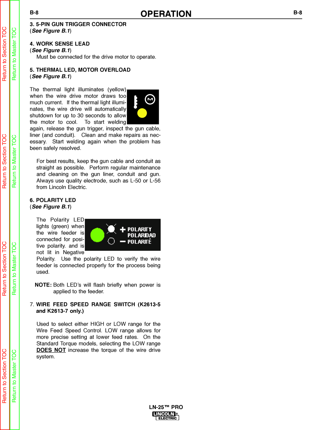
6.POLARITY LED (See Figure B.1)
The Polarity LED lights (green) when the wire feeder is connected for posi- tive polarity. and is not lit in Negative
Polarity. Use the polarity LED to verify the wire feeder is connected properly for the process being used.
NOTE: Both LED’s will flash briefly when power is applied to the feeder.
7.WIRE FEED SPEED RANGE SWITCH (K2613-5 and K2613-7 only.)
Used to select either HIGH or LOW range for the Wire Feed Speed Control. LOW range allows for more precise setting at lower feed rates. On the Standard Torque models, selecting the LOW range DOES NOT increase the torque of the wire drive system.