Return to Section TOC
Return to Section TOC
TOC
Return to Master TOC
Return to Master TOC
TOC
TROUBLESHOOTING & REPAIR | ||
|
CONTACTOR REMOVAL AND REPLACEMENT PROCEDURE (CONTINUED)
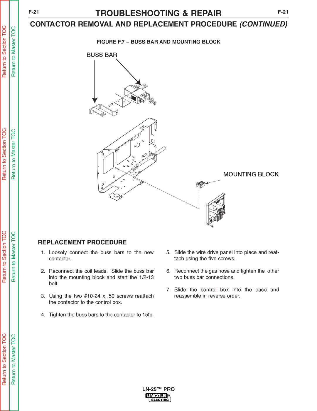
FIGURE F.7 – BUSS BAR AND MOUNTING BLOCK
BUSS BAR
MOUNTING BLOCK
REPLACEMENT PROCEDURE
Return to Master
1.Loosely connect the buss bars to the new contactor.
2.Reconnect the coil leads. Slide the buss bar into the mounting block and start the
3.Using the two
5.Slide the wire drive panel into place and reat- tach using the five screws.
6.Reconnect the gas hose and tighten the other two buss bar connections.
7.Slide the control box into the case and reassemble in reverse order.
Return to Section TOC
Return to Master TOC
4. Tighten the buss bars to the contactor to 15fp.