Return to Section TOC
Return to Section TOC
Return to Section TOC
Return to Section TOC
Return to Master TOC
Return to Master TOC
Return to Master TOC
Return to Master TOC
OPERATION | ||||
5. Output / Parameter Adjust Knob- Allows you to |
| 2 STEP DIAGRAM 1 | ||
|
| |||
continuously adjust the current both in TIG and in Stick |
| (1) | ||
welding. Allows you to change the value, shown on |
|
| ||
"Digital Display Item 6", of the parameter selected with |
|
| ||
"Setup/Parameter select button Item 4". |
|
|
| |
6. Digital Display - displays currently set values for |
|
| ||
each mode or welding parameter. |
|
|
| |
7. Local/Remote push button - Selects the welding |
|
| ||
current adjusting system: |
| Possible variations of this standard sequence is shown | ||
• from front panel |
| in (2 step diagram 2). It is possible to press and hold | ||
• from remote control |
| the TIG torch trigger a second time during downslope | ||
The LED beside the symbol confirms the selection. | to restart. After the trigger is pressed the output current | |||
|
| will increase to the welding current. This operation is | ||
8. Tig Trigger Sequences - |
| shown in (2 step diagram 2). | ||
For the |
| 2 STEP DIAGRAM 2 | ||
either the |
| |||
(1) | (2) | |||
the Trigger Mode Push Button. |
| |||
|
|
| ||
|
|
|
| |
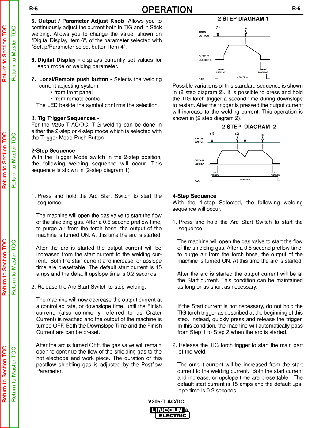
With the Trigger Mode switch in the |
|
| ||
the following welding sequence will occur. This |
|
| ||
sequence is shown in |
|
|
| |
1. Press and hold the Arc Start Switch to start the | |
sequence. | With the |
| sequence will occur. |
The machine will open the gas valve to start the flow |
|
of the shielding gas. After a 0.5 second preflow time, | 1. Press and hold the Arc Start Switch to start the |
to purge air from the torch hose, the output of the | sequence. |
machine is turned ON. At this time the arc is started. |
|
| The machine will open the gas valve to start the flow |
After the arc is started the output current will be | of the shielding gas. After a 0.5 second preflow time, |
increased from the start current to the welding cur- | to purge air from the torch hose, the output of the |
rent. Both the start current and increase, or upslope | machine is turned ON. At this time the arc is started. |
time are presettable. The default start current is 15 |
|
amps and the default upslope time is 0.2 seconds. | After the arc is started the output current will be at |
| the Start current. This condition can be maintained |
2. Release the Arc Start Switch to stop welding. | as long or as short as necessary. |
The machine will now decrease the output current at |
|
a controlled rate, or downslope time, until the Finish | If the Start current is not necessary, do not hold the |
current, (also commonly referred to as Crater | TIG torch trigger as described at the beginning of this |
Current) is reached and the output of the machine is | step. Instead, quickly press and release the trigger. |
turned OFF. Both the Downslope Time and the Finish | In this condition, the machine will automatically pass |
Current are can be preset. | from Step 1 to Step 2 when the arc is started. |
After the arc is turned OFF, the gas valve will remain | 2. Release the TIG torch trigger to start the main part |
open to continue the flow of the shielding gas to the | of the weld. |
hot electrode and work piece. The duration of this |
|
postflow shielding gas is adjusted by the Postflow | The output current will be increased from the start |
Parameter. | current to the welding current. Both the start current |
| and increase, or upslope time are presettable. The |
| default start current is 15 amps and the default ups- |
| lope time is 0.2 seconds. |