Return to Section TOC
Return to Section TOC
Return to Master TOC
Return to Master TOC
TROUBLESHOOTING & REPAIR
INPUT FILTER BOARD TEST (continued)
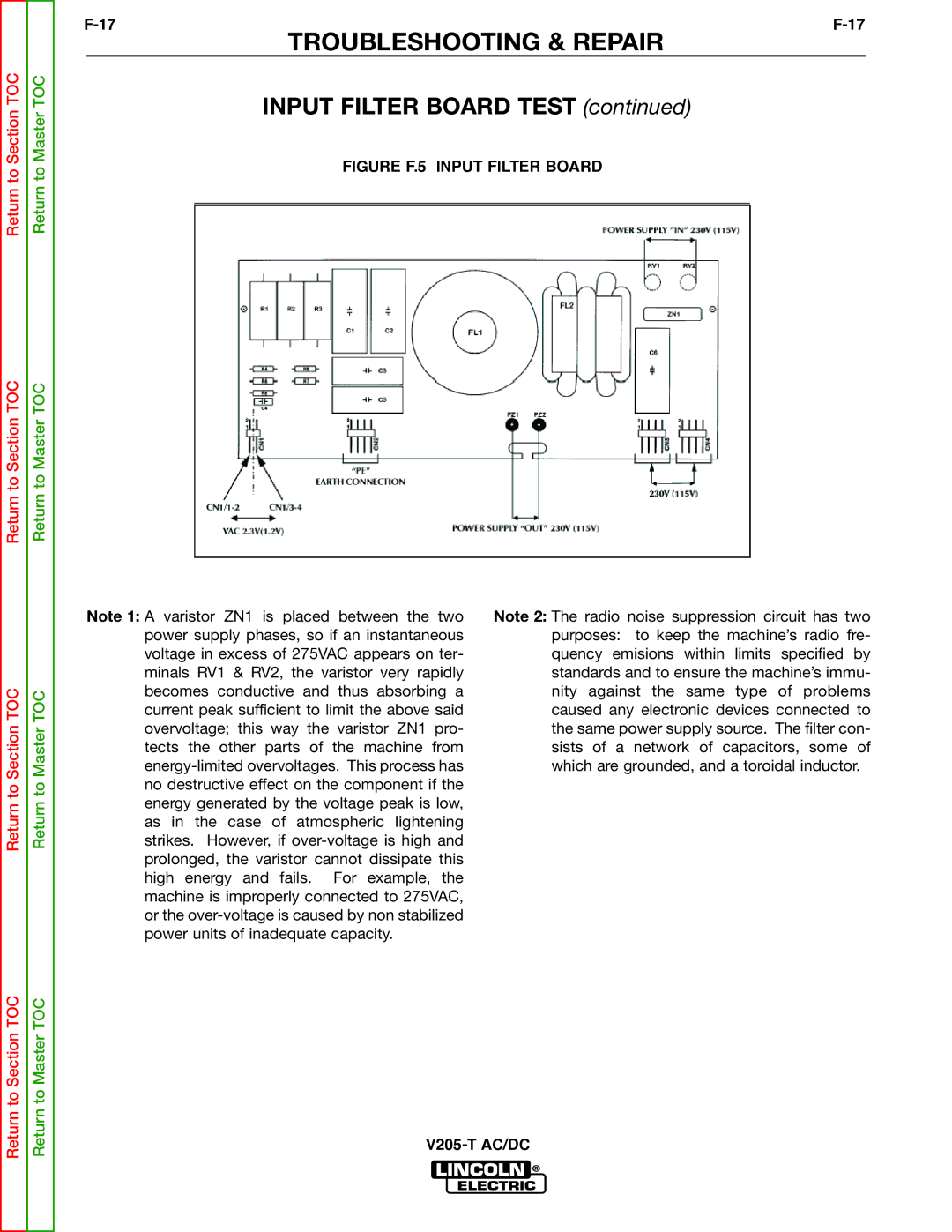
FIGURE F.5 INPUT FILTER BOARD
Return to Section TOC
Return to Master TOC
Note 1: A varistor ZN1 is placed between the two power supply phases, so if an instantaneous voltage in excess of 275VAC appears on ter- minals RV1 & RV2, the varistor very rapidly becomes conductive and thus absorbing a current peak sufficient to limit the above said overvoltage; this way the varistor ZN1 pro- tects the other parts of the machine from
Note 2: The radio noise suppression circuit has two purposes: to keep the machine’s radio fre- quency emisions within limits specified by standards and to ensure the machine’s immu- nity against the same type of problems caused any electronic devices connected to the same power supply source. The filter con- sists of a network of capacitors, some of which are grounded, and a toroidal inductor.
Return to Section TOC
Return to Master TOC