Return to Section TOC
Return to Master TOC
TROUBLESHOOTING & REPAIR
MAIN INVERTER BOARD “UPFR” SECTION TEST (continued)
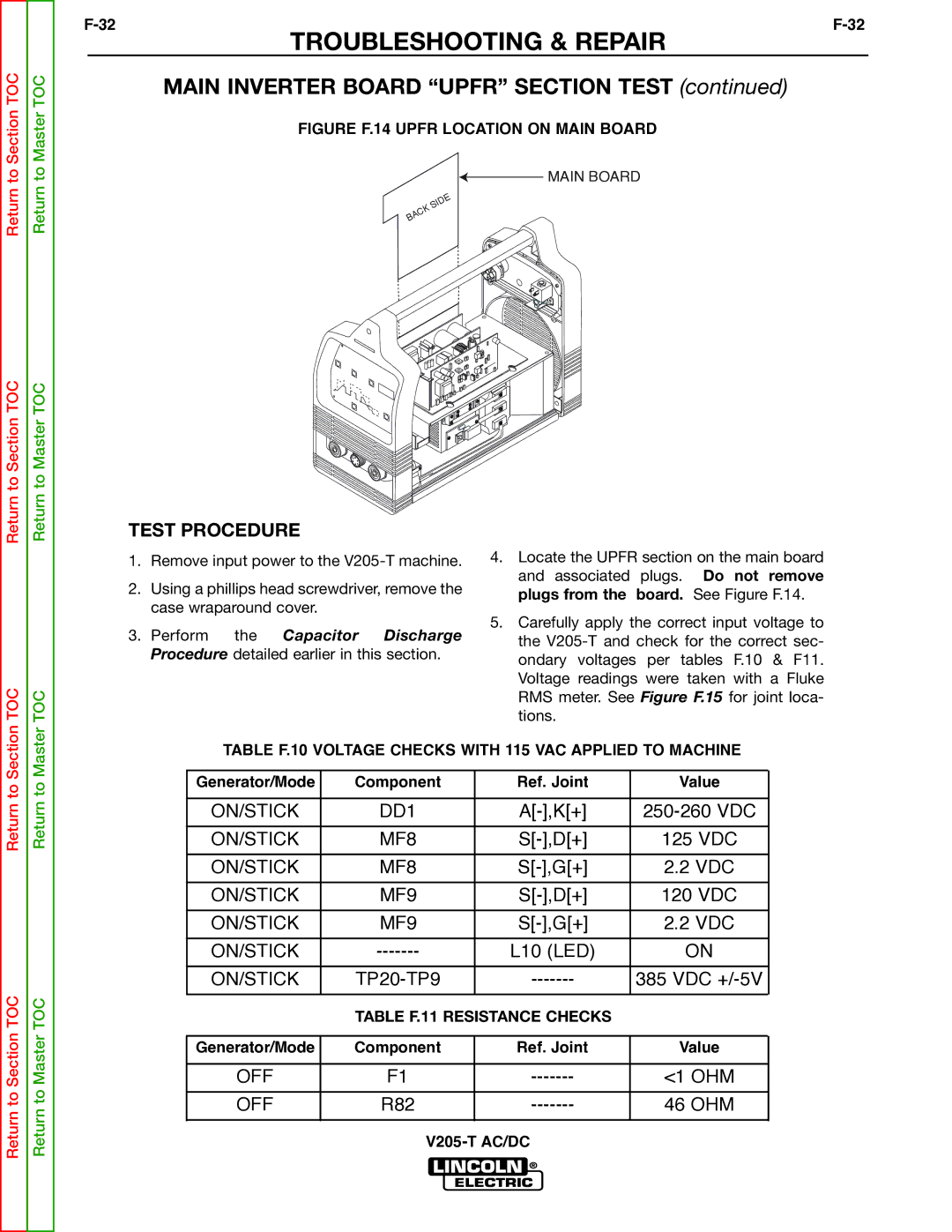
FIGURE F.14 UPFR LOCATION ON MAIN BOARD
![]() MAIN BOARD
MAIN BOARD
Return to Section TOC
TOC
Return to Master TOC
TOC
TEST PROCEDURE
1.Remove input power to the
2.Using a phillips head screwdriver, remove the case wraparound cover.
3.Perform the Capacitor Discharge Procedure detailed earlier in this section.
4.Locate the UPFR section on the main board and associated plugs. Do not remove plugs from the board. See Figure F.14.
5.Carefully apply the correct input voltage to the
Return to Section
Return to Section TOC
Return to Master
Return to Master TOC
TABLE F.10 VOLTAGE CHECKS WITH 115 VAC APPLIED TO MACHINE
Generator/Mode | Component | Ref. Joint | Value |
|
|
|
|
ON/STICK | DD1 | ||
|
|
|
|
ON/STICK | MF8 | 125 VDC | |
|
|
|
|
ON/STICK | MF8 | 2.2 VDC | |
|
|
|
|
ON/STICK | MF9 | 120 VDC | |
|
|
|
|
ON/STICK | MF9 | 2.2 VDC | |
|
|
|
|
ON/STICK | L10 (LED) | ON | |
|
|
|
|
ON/STICK | 385 VDC | ||
|
|
|
|
| TABLE F.11 RESISTANCE CHECKS |
| |
|
|
|
|
Generator/Mode | Component | Ref. Joint | Value |
|
|
|
|
OFF | F1 | <1 OHM | |
|
|
|
|
OFF | R82 | 46 OHM | |
|
|
|
|