Return to Section TOC
Return to Section TOC
Return to Master TOC
Return to Master TOC
THEORY OF OPERATION
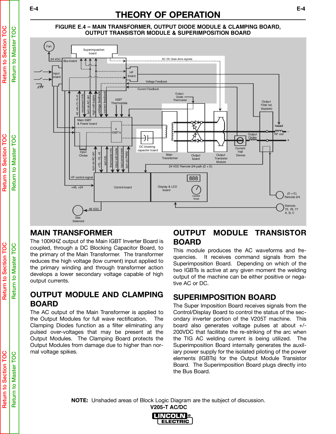
FIGURE E.4 – MAIN TRANSFORMER, OUTPUT DIODE MODULE & CLAMPING BOARD,
OUTPUT TRANSISTOR MODULE & SUPERIMPOSITION BOARD
Fan |
|
|
|
|
|
|
|
|
|
|
|
|
|
|
|
|
| Superimposition |
|
|
|
|
|
|
|
|
| ||||
|
|
| board |
|
|
|
|
|
|
|
|
|
|
| |
24 VDC | Bus board |
|
|
|
|
|
|
|
|
| AC DC Gate drive signals |
|
|
| |
Input |
|
|
|
|
|
|
|
|
|
| HF |
|
|
|
|
|
|
|
|
|
|
|
|
|
| board |
|
|
|
| |
board |
|
|
|
|
|
|
|
|
|
|
|
|
|
| |
|
|
|
|
|
|
|
|
|
|
|
|
|
|
| |
|
|
|
|
|
|
|
|
|
|
| Voltage Feedback |
|
|
|
|
| info.reconnect | ckt.AConturn | supplyvolthigh | feedbackvoltage | feedbackcurrent |
|
|
|
| Current Feedback |
|
|
|
| |
|
|
|
|
| Output |
|
|
|
| ||||||
|
|
|
|
|
|
|
|
|
|
|
|
|
|
| |
|
|
|
|
|
|
|
| IGBT |
| Diode |
|
|
|
| |
|
|
|
|
|
|
|
|
| Thermostat |
|
|
| Output | ||
|
|
|
|
|
|
| Thermostats |
|
|
|
| ||||
|
|
|
|
|
|
|
|
|
|
| Filter bd. | ||||
|
|
|
|
|
|
|
|
|
|
|
|
|
|
| |
|
|
|
|
|
|
|
|
|
|
|
|
|
|
| (bypass) |
| Main IGBT |
|
|
|
|
|
|
|
|
|
|
|
| ||
| & Power board |
|
|
|
|
|
|
|
|
|
|
| |||
|
|
|
|
|
|
|
| 4 |
|
|
|
|
|
| _ |
|
|
|
|
|
|
| IGBT’s |
|
|
|
| Output | RF coil | ||
|
|
|
|
|
|
|
|
|
|
|
|
|
| ||
|
|
|
|
|
|
|
|
|
|
|
|
|
| Choke | + |
|
|
|
|
|
|
|
|
|
|
|
|
|
|
| |
|
|
|
|
|
|
| infothermostat | metervoltinput | metercurrentinput |
| DC blocking |
|
| Current |
|
|
|
|
| ckt.AConturn | infoset | PWMonturn | capacitor board |
|
|
| |||||
|
| Input |
|
|
| Hall |
| ||||||||
|
|
|
|
|
|
|
|
|
|
|
|
| |||
|
|
|
|
|
|
|
|
|
| Main |
| Output |
| ||
|
| Choke |
|
|
|
|
|
|
| Output | Device |
| |||
|
|
|
|
|
|
|
|
|
|
| Transformer | board | Transistor |
|
|
|
|
|
|
|
|
|
|
|
|
|
|
| Module |
|
|
|
|
|
|
|
|
|
|
|
|
| 24 VDC Remote 2/4 path (D + E) |
|
|
| |
| HF control signal |
|
|
|
|
|
|
| 888 |
|
|
| |||
|
|
|
|
|
|
|
|
|
|
|
| ||||
+48, +24 | Control board | Display & LED |
|
| board |
Control |
| (D + E) |
| Remote 2/4 | |
Knob |
| |
|
|
Remote
48 VDC75, 76, 77 A, B, C
Gas
Solenoid
Return to Section TOC
Return to Master TOC
MAIN TRANSFORMER
The 100KHZ output of the Main IGBT Inverter Board is coupled, through a DC Blocking Capacitor Board, to the primary of the Main Transformer. The transformer reduces the high voltage (low current) input applied to the primary winding and through transformer action develops a lower secondary voltage capable of high output currents.
OUTPUT MODULE TRANSISTOR BOARD
This module produces the AC waveforms and fre- quencies. It receives command signals from the Superimposition Board. Depending on which of the two IGBTs is active at any given moment the welding output of the machine can be either positive or nega- tive AC or DC.
to Section TOC
to Master TOC
OUTPUT MODULE AND CLAMPING BOARD
The AC output of the Main Transformer is applied to the Output Modules for full wave rectification. The Clamping Diodes function as a filter eliminating any pulsed
SUPERIMPOSITION BOARD
The Super Imposition Board receives signals from the Control/Display Board to control the status of the sec- ondary inverter portion of the V205T machine. This board also generates voltage pulses at about +/- 200VDC that facilitate the
Return
Return
NOTE: Unshaded areas of Block Logic Diagram are the subject of discussion.