Return to Master TOC
Return to Master TOC
Return to Master TOC
Return to Master TOC
Section | Section |
TABLE OF CONTENTS
-THEORY OF OPERATION SECTION-
Theory of Operation | Section E |
General Description | |
Input Board and Bus Board | |
Main IGBT Inverter Board | |
Main Transformer | |
Output Module and Clamping Board | |
Output Module Transistor Board | |
Superimposition Board | |
Control/Display Board | |
High Frequency Board | |
Output Filter Board | |
Insulated Gate Bipolar Transistor (IGBT) Operation |
|
|
|
|
|
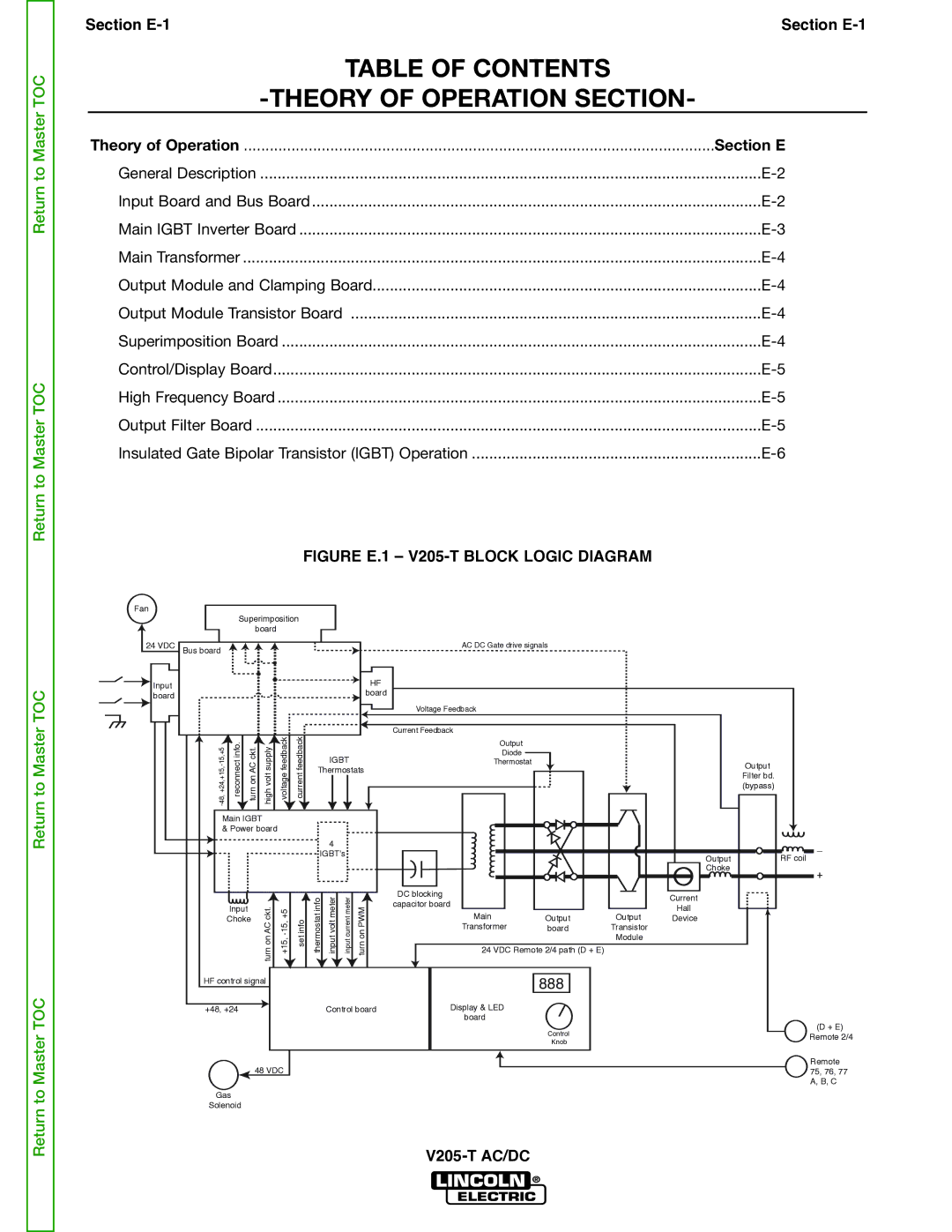
| FIGURE E.1 – |
|
| |||||||
Fan |
|
|
|
|
|
|
|
|
|
|
|
|
|
|
|
|
| Superimposition |
|
|
|
|
|
|
|
|
| ||||
|
|
| board |
|
|
|
|
|
|
|
|
|
|
| |
24 VDC | Bus board |
|
|
|
|
|
|
|
|
| AC DC Gate drive signals |
|
|
| |
Input |
|
|
|
|
|
|
|
|
|
| HF |
|
|
|
|
|
|
|
|
|
|
|
|
|
| board |
|
|
|
| |
board |
|
|
|
|
|
|
|
|
|
|
|
|
|
| |
|
|
|
|
|
|
|
|
|
|
|
|
|
|
| |
|
|
|
|
|
|
|
|
|
|
| Voltage Feedback |
|
|
|
|
| info.reconnect | ckt.AConturn | supplyvolthigh | feedbackvoltage | feedbackcurrent |
|
|
|
| Current Feedback |
|
|
|
| |
|
|
|
|
| Output |
|
|
|
| ||||||
|
|
|
|
|
|
|
|
|
|
|
|
|
|
| |
|
|
|
|
|
|
|
| IGBT |
| Diode |
|
|
|
| |
|
|
|
|
|
|
|
|
| Thermostat |
|
|
| Output | ||
|
|
|
|
|
|
| Thermostats |
|
|
|
| ||||
|
|
|
|
|
|
|
|
|
|
| Filter bd. | ||||
|
|
|
|
|
|
|
|
|
|
|
|
|
|
| |
|
|
|
|
|
|
|
|
|
|
|
|
|
|
| (bypass) |
| Main IGBT |
|
|
|
|
|
|
|
|
|
|
|
| ||
| & Power board |
|
|
|
|
|
|
|
|
|
|
| |||
|
|
|
|
|
|
|
| 4 |
|
|
|
|
|
| _ |
|
|
|
|
|
|
| IGBT’s |
|
|
|
| Output | RF coil | ||
|
|
|
|
|
|
|
|
|
|
|
|
|
| ||
|
|
|
|
|
|
|
|
|
|
|
|
|
| Choke | + |
|
|
|
|
|
|
|
|
|
|
|
|
|
|
| |
|
|
|
|
|
|
| infothermostat | metervoltinput | metercurrentinput |
| DC blocking |
|
| Current |
|
|
|
|
| ckt.AConturn | infoset | PWMonturn | capacitor board |
|
|
| |||||
|
| Input |
|
|
| Hall |
| ||||||||
|
|
|
|
|
|
|
|
|
|
|
|
| |||
|
|
|
|
|
|
|
|
|
| Main |
| Output |
| ||
|
| Choke |
|
|
|
|
|
|
| Output | Device |
| |||
|
|
|
|
|
|
|
|
|
|
| Transformer | board | Transistor |
|
|
|
|
|
|
|
|
|
|
|
|
|
|
| Module |
|
|
|
|
|
|
|
|
|
|
|
|
| 24 VDC Remote 2/4 path (D + E) |
|
|
| |
| HF control signal |
|
|
|
|
|
|
| 888 |
|
|
| |||
|
|
|
|
|
|
|
|
|
|
|
| ||||
+48, +24 | Control board | Display & LED |
|
| board |
Control |
| (D + E) |
| Remote 2/4 | |
Knob |
| |
|
|
Remote
48 VDC75, 76, 77 A, B, C
Gas
Solenoid