Chapter 2
MiniGBIC
To establish a Gigabit Ethernet connection using a miniGBIC port, you will need to install a MGBT1, MGBSX2, or MGBLH1 Gigabit expansion module and use Category 5e cabling or fiber optic cabling..
To establish a Fast Ethernet connection using a miniGBIC port, you will need to install a MFEFX1
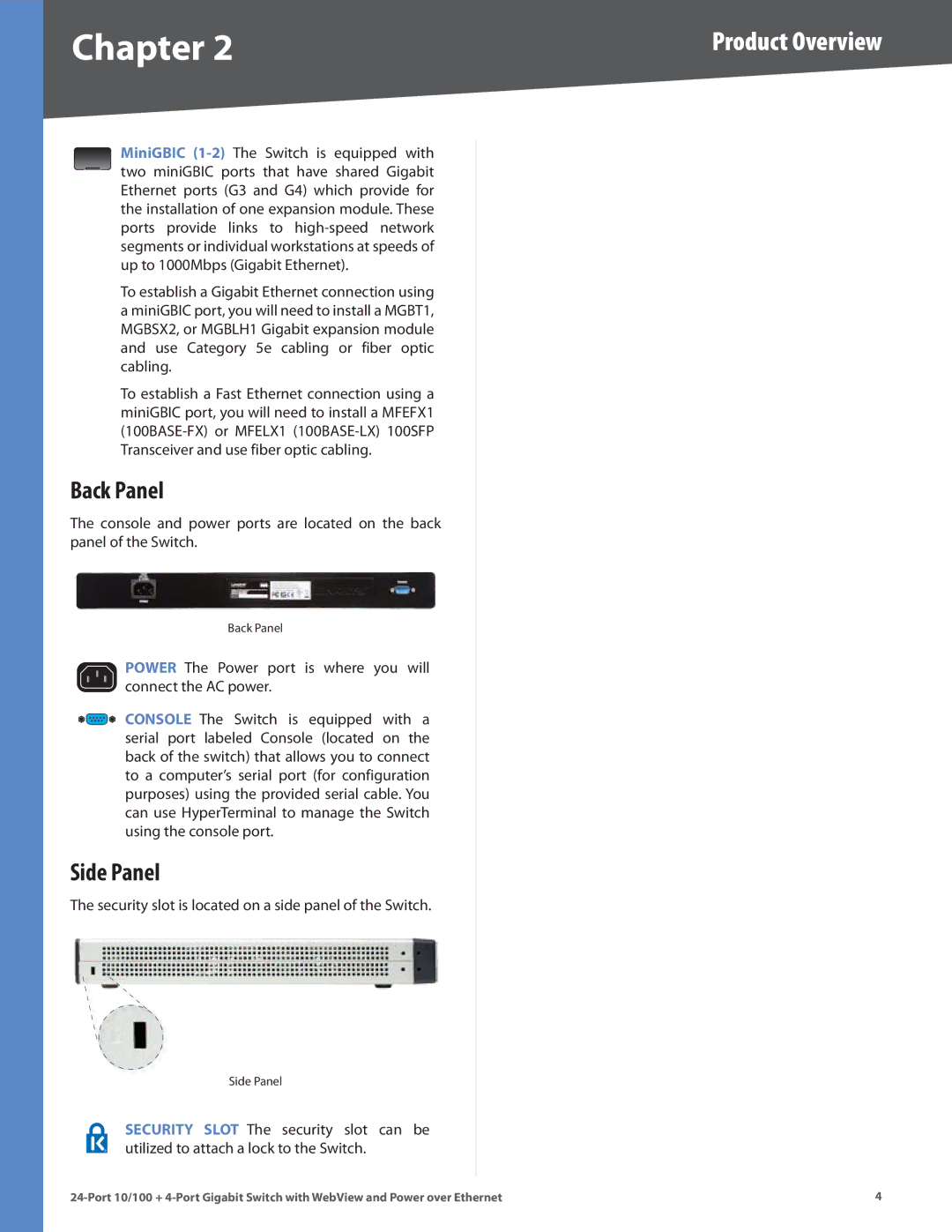
Back Panel
The console and power ports are located on the back panel of the Switch..
Back Panel
POWER The Power port is where you will connect the AC power..
CONSOLE The Switch is equipped with a serial port labeled Console (located on the back of the switch) that allows you to connect to a computer’s serial port (for configuration purposes) using the provided serial cable.. You can use HyperTerminal to manage the Switch using the console port..
Side Panel
The security slot is located on a side panel of the Switch..
Side Panel
SECURITY SLOT The security slot can be utilized to attach a lock to the Switch..