Wireless-G Ethernet Bridge with 5-Port Switch
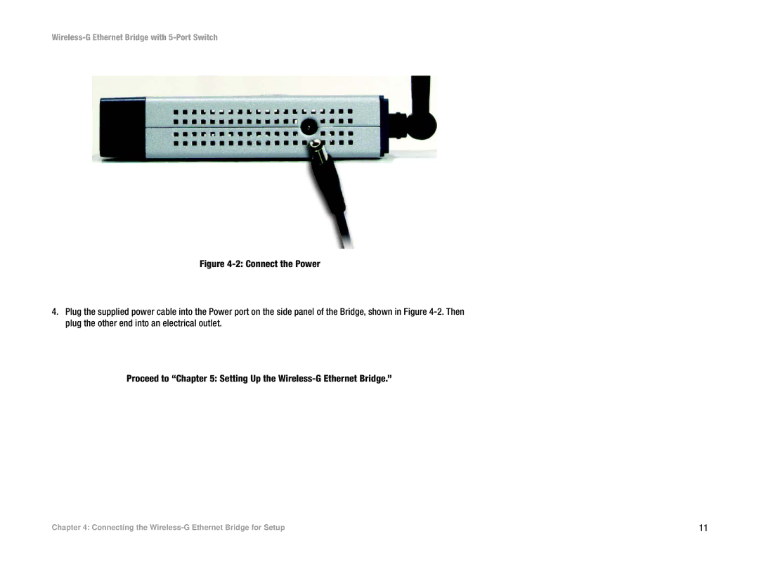
Figure 4-2: Connect the Power
4.Plug the supplied power cable into the Power port on the side panel of the Bridge, shown in Figure 4-2. Then plug the other end into an electrical outlet.
Proceed to “Chapter 5: Setting Up the Wireless-G Ethernet Bridge.”
Chapter 4: Connecting the | 11 |