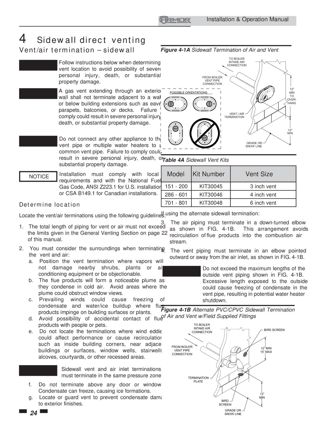
151 specifications
Lochinvar 151,286 is a notable model in the realm of commercial water heating solutions, designed primarily for large-scale applications. This model incorporates advanced technologies and features that set it apart in terms of efficiency, usability, and reliability.One of the hallmark features of Lochinvar 151,286 is its high-efficiency system that leverages condensing technology. This technology enables the unit to extract additional heat from exhaust gases, allowing it to operate at an impressive annual fuel utilization efficiency (AFUE) rating. This not only reduces energy consumption, but it also significantly lowers operational costs.
The Lochinvar 151,286 is equipped with a robust stainless steel heat exchanger, which provides both durability and enhanced thermal efficiency. This design withstands the rigors of high-demand environments, making it ideal for restaurants, schools, hospitals, or any facility requiring consistent hot water supply. Its compact footprint allows it to be installed in tight spaces without sacrificing performance.
Another standout characteristic is its intelligent control system. The built-in touchscreen interface offers users an intuitive way to manage settings, monitor performance, and troubleshoot issues. This smart technology aids in simplifying maintenance and improves overall system reliability. The unit also features advanced safety protocols, including multiple sensors that monitor operation and provide alerts in case of irregular performance.
In terms of capacity, the Lochinvar 151,286 can deliver an impressive output, accommodating varying demands with ease. Its innovative modulation capabilities allow the unit to adjust its heating output based on real-time hot water needs, ensuring unmatched comfort and efficiency.
Supporting the model’s performance are versatile connectivity options. Lochinvar 151,286 can integrate seamlessly with building management systems, allowing facility managers to monitor and control heating processes remotely. This level of connectivity not only enhances control but also supports energy-saving strategies across the facility.
In conclusion, Lochinvar 151,286 stands out as a premium choice for commercial water heating needs. With its high-efficiency ratings, durable construction, intelligent control system, impressive capacity, and versatile connectivity, it ensures that hot water is delivered reliably and efficiently, meeting the demands of modern businesses while reducing energy costs. This combination of technology and design makes it an essential component for any large-scale facility focused on performance and sustainability.

