Installation & Operation Manual

4 Sidewall direct venting (continued)

Sidewall termination – optional concentric vent: Models 151 - 601

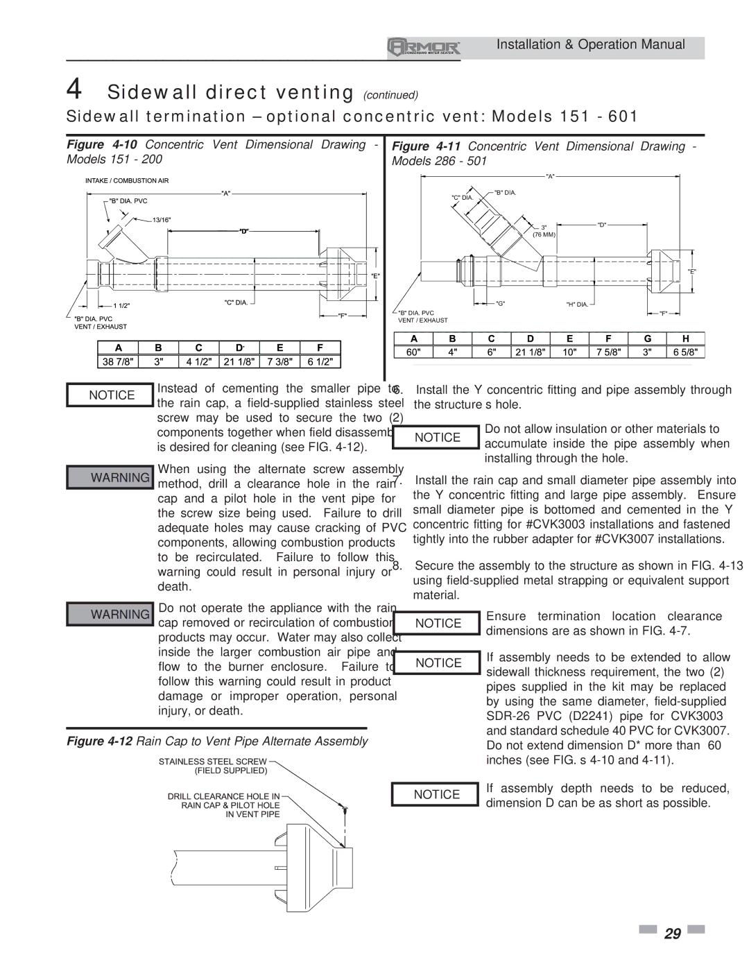
Figure 4-10Concentric Vent Dimensional Drawing -

Figure 4-11 Concentric

Vent

Dimensional

Drawing

-

Models 151 - 200

Models 286 - 501


"A"


"C" DIA.

"B" DIA.


3"


"D"


(76 MM)


"E"


"G"


"H" DIA.


"B" DIA. PVC


"F"


VENT / EXHAUST


A

B

C


D


E

F


G

H


60"

4"

6"

21 1/8"


10"

7 5/8"


3"

6 5/8"


(1524 MM)

(102 MM)

(152 MM)

(537 MM)

(254 MM)

(194 MM)

(76 MM)

(168 MM)

NOTICE

Instead of cementing the smaller pipe to

the rain cap, a field-supplied stainless steel


screw may be used to secure the two (2)


components together when field disassembly


is desired for cleaning (see FIG. 4-12).

6.Install the Y concentric fitting and pipe assembly through the structure’s hole.

Do not allow insulation or other materials to NOTICE accumulate inside the pipe assembly when

installing through the hole.

￿WARNING

￿WARNING

When using the alternate screw assembly method, drill a clearance hole in the rain cap and a pilot hole in the vent pipe for the screw size being used. Failure to drill adequate holes may cause cracking of PVC components, allowing combustion products to be recirculated. Failure to follow this warning could result in personal injury or death.

Do not operate the appliance with the rain cap removed or recirculation of combustion products may occur. Water may also collect inside the larger combustion air pipe and flow to the burner enclosure. Failure to follow this warning could result in product damage or improper operation, personal injury, or death.

7.Install the rain cap and small diameter pipe assembly into the Y concentric fitting and large pipe assembly. Ensure small diameter pipe is bottomed and cemented in the Y concentric fitting for #CVK3003 installations and fastened tightly into the rubber adapter for #CVK3007 installations.

8.Secure the assembly to the structure as shown in FIG. 4-13 using field-supplied metal strapping or equivalent support material.

NOTICE

Ensure termination location clearance

dimensions are as shown in FIG. 4-7.


If assembly needs to be extended to allow

NOTICE

sidewall thickness requirement, the two (2)


pipes supplied in the kit may be replaced


by using the same diameter, field-supplied


SDR-26 PVC (D2241) pipe for CVK3003


and standard schedule 40 PVC for CVK3007.

Figure 4-12Rain Cap to Vent Pipe Alternate Assembly


Do not extend dimension D* more than 60


inches (see FIG.’s 4-10 and 4-11).


If assembly depth needs to be reduced,

NOTICE

dimension D can be as short as possible.


29

Page 29
Image 29
Lochinvar 151 operation manual Concentric

151 specifications

Lochinvar 151,286 is a notable model in the realm of commercial water heating solutions, designed primarily for large-scale applications. This model incorporates advanced technologies and features that set it apart in terms of efficiency, usability, and reliability.

One of the hallmark features of Lochinvar 151,286 is its high-efficiency system that leverages condensing technology. This technology enables the unit to extract additional heat from exhaust gases, allowing it to operate at an impressive annual fuel utilization efficiency (AFUE) rating. This not only reduces energy consumption, but it also significantly lowers operational costs.

The Lochinvar 151,286 is equipped with a robust stainless steel heat exchanger, which provides both durability and enhanced thermal efficiency. This design withstands the rigors of high-demand environments, making it ideal for restaurants, schools, hospitals, or any facility requiring consistent hot water supply. Its compact footprint allows it to be installed in tight spaces without sacrificing performance.

Another standout characteristic is its intelligent control system. The built-in touchscreen interface offers users an intuitive way to manage settings, monitor performance, and troubleshoot issues. This smart technology aids in simplifying maintenance and improves overall system reliability. The unit also features advanced safety protocols, including multiple sensors that monitor operation and provide alerts in case of irregular performance.

In terms of capacity, the Lochinvar 151,286 can deliver an impressive output, accommodating varying demands with ease. Its innovative modulation capabilities allow the unit to adjust its heating output based on real-time hot water needs, ensuring unmatched comfort and efficiency.

Supporting the model’s performance are versatile connectivity options. Lochinvar 151,286 can integrate seamlessly with building management systems, allowing facility managers to monitor and control heating processes remotely. This level of connectivity not only enhances control but also supports energy-saving strategies across the facility.

In conclusion, Lochinvar 151,286 stands out as a premium choice for commercial water heating needs. With its high-efficiency ratings, durable construction, intelligent control system, impressive capacity, and versatile connectivity, it ensures that hot water is delivered reliably and efficiently, meeting the demands of modern businesses while reducing energy costs. This combination of technology and design makes it an essential component for any large-scale facility focused on performance and sustainability.