Installation & Operation Manual

13 Diagrams

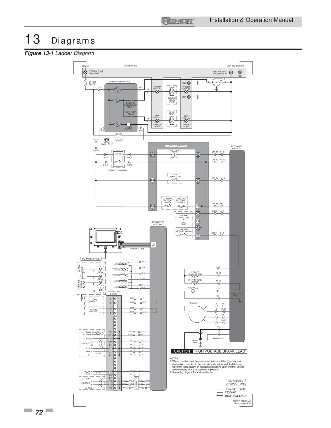
Figure 13-1Ladder Diagram

120VAC


JUNCTION BOX


NEUTRAL GROUND

TERMINAL STRIP


TERMINAL STRIP

120V SUPPLY "L"


120V SUPPLY "N"


1

2

ON / OFF

INTEGRATED CONTROL


GND

BLOWER

SWITCH


X1-6

F2

X1-1

SYSTEM

SYSTEM


3


X1-2

PUMP "L"

PUMP "N"


3.15A


F1


GND


BUILDING


RECIRC


5A

BUILDING


PUMP


RECIRC PUMP


RELAY


DHW PUMP


DHW


RELAY

DHW

PUMP


DHW


X1-3

PUMP "L"

PUMP "N"


F3


TERMINAL

TERMINAL


.8A

24V DC

STRIP

STRIP


X5-9


SUPPLY


X5-1


120 VAC


X4-3

24 VAC


3.5A


AW 801 ONLY


CONNECTION BOARD


INTEGRATED


CN5-5


CONTROL


FLOW

CN5-14

X4-8


LWCO


CN7-1


CN7-4

11

SWITCH

12


CN5-10

X4-12

CN7-3


CN7-2


CONNECTION BOARD


TANK


THERMOSTAT


CN5-12 X4-10


13


14


LOW GAS

HIGH GAS


PRESSURE PRESSURE


SWITCH

SWITCH


CN5-11 X4-11


10


9

CN5-3 X4-5


LOUVER


5


RELAY COIL


INTEGRATED

24VAC


6


CONTROL


LOUVER


7


PROVING SWITCH

CN5-4

X4-4


8


X7


RIBBON CABLE


PC INTERFACE


S2


X5-6


INLET


ALARM BELL

1

SENSOR


OPERATING

S1a


X5-4


X5-2


SENSOR


S1b


X5-12


BLOCKED

X5-10


HIGH LIMIT


DRAIN SWITCH


2

SENSOR


SILENCING SWITCH

FLUE

S3a


X5-5


AIR PRESSURE


X5-14


X2-2


SENSOR


GAS VALVE


6


SWITCH


S3b


X5-13


FLUE


SENSOR


13

CONNECTION


BOARD


GAS VALVE


CN5-1


X4-7


X2-1

RELAY

ALARM

1


CONTACTS

2


CN5-8


X4-14


BLOWER

1

X5-7


3


CN5-2


X4-6


2

X5-16

RUN-TIME


CONTACTS

4


CN5-9


X4-13


4

X5-8


5

X5-15


TR2


TANK

S4

16


CN3-9


X4-9


X1-7


SENSOR


17


CN3-6


X4-6


SHIELD


19


CN6


SPARK

FLAME ROD

A


20


X6


ROD


CASCADE


21


CN6


X6


B


SHIELD


22


CN6


X6


CAUTION


HIGH VOLTAGE SPARK LEAD

BMS +


23


CN6


X6


IN -

0-10V

24


CN6


X6


NOTES:


1. Where possible, switches are shown without utilities (gas, water or


electricity) connected to the unit. As such, actual switch states may


vary from those shown on diagrams depending upon whether utilities

RATE +


25


CN6


X6


are connected or a fault condition is present.

0-10V


2. See wiring diagram for additional notes.


OUT -


26


CN6

M

X6


SHIELD


27


A


28

CN8-1

X6-1

O

X4-1

X9-2


BOX DEPICTS


D


MODBUS


29

CN8-2

X6-2

B

X4-2

X9-1


OPTIONAL ITEMS

B


SHIELD


30

CN8-3

X6-3

U

X4-3

X9-3


LOW VOLTAGE


S


120 VAC


HIGH VOLTAGE

LADDER DIAGRAM

LBL20149 REV B

72

Page 72
Image 72
Lochinvar 151 operation manual Diagrams, PC Interface

151 specifications

Lochinvar 151,286 is a notable model in the realm of commercial water heating solutions, designed primarily for large-scale applications. This model incorporates advanced technologies and features that set it apart in terms of efficiency, usability, and reliability.

One of the hallmark features of Lochinvar 151,286 is its high-efficiency system that leverages condensing technology. This technology enables the unit to extract additional heat from exhaust gases, allowing it to operate at an impressive annual fuel utilization efficiency (AFUE) rating. This not only reduces energy consumption, but it also significantly lowers operational costs.

The Lochinvar 151,286 is equipped with a robust stainless steel heat exchanger, which provides both durability and enhanced thermal efficiency. This design withstands the rigors of high-demand environments, making it ideal for restaurants, schools, hospitals, or any facility requiring consistent hot water supply. Its compact footprint allows it to be installed in tight spaces without sacrificing performance.

Another standout characteristic is its intelligent control system. The built-in touchscreen interface offers users an intuitive way to manage settings, monitor performance, and troubleshoot issues. This smart technology aids in simplifying maintenance and improves overall system reliability. The unit also features advanced safety protocols, including multiple sensors that monitor operation and provide alerts in case of irregular performance.

In terms of capacity, the Lochinvar 151,286 can deliver an impressive output, accommodating varying demands with ease. Its innovative modulation capabilities allow the unit to adjust its heating output based on real-time hot water needs, ensuring unmatched comfort and efficiency.

Supporting the model’s performance are versatile connectivity options. Lochinvar 151,286 can integrate seamlessly with building management systems, allowing facility managers to monitor and control heating processes remotely. This level of connectivity not only enhances control but also supports energy-saving strategies across the facility.

In conclusion, Lochinvar 151,286 stands out as a premium choice for commercial water heating needs. With its high-efficiency ratings, durable construction, intelligent control system, impressive capacity, and versatile connectivity, it ensures that hot water is delivered reliably and efficiently, meeting the demands of modern businesses while reducing energy costs. This combination of technology and design makes it an essential component for any large-scale facility focused on performance and sustainability.