Installation & Service Manual
2Venting
The distance of the vent terminal from adjacent buildings, windows that open and building openings MUST comply with the latest edition of the National Fuel Gas Code, ANSI Z223.1, in Canada, the latest edition of CGA Standard B149 Installation Code for Gas Burning Appliances and Equipment.
Vent connection is made directly to the top of the appliance. This appliance is designed with a
A Conventional Negative Draft Venting System
The negative draft in a conventional vent installation must be within the range of a negative 0.02 to 0.05 inches water column to ensure proper operation. All draft readings are made while the appliance is in stable operation (approximately 2 to 5 minutes).
Multiple appliance installations with combined venting or common venting with other negative draft appliances require that each appliance must have draft within the proper range. If the draft measured above the appliance’s
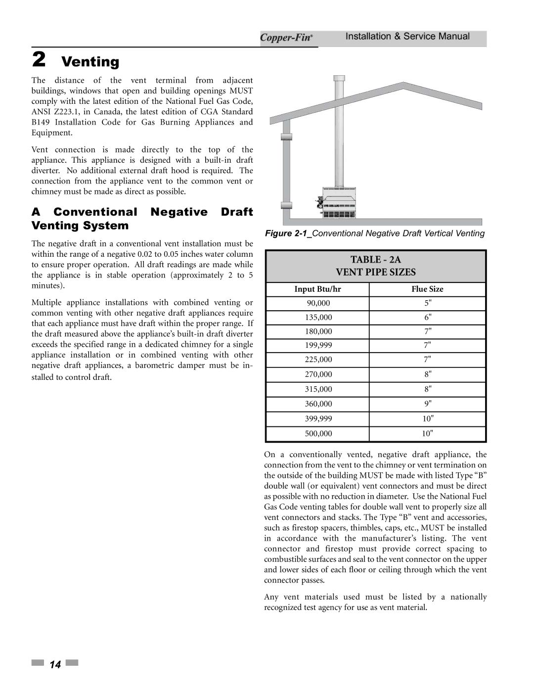
Figure 2-1_Conventional Negative Draft Vertical Venting
TABLE - 2A
VENT PIPE SIZES
| Input Btu/hr | Flue Size |
|
|
|
|
|
| 90,000 | 5" |
|
|
|
|
|
| 135,000 | 6" |
|
|
|
|
|
| 180,000 | 7" |
|
|
|
|
|
| 199,999 | 7" |
|
|
|
|
|
| 225,000 | 7" |
|
|
|
|
|
| 270,000 | 8" |
|
|
|
|
|
| 315,000 | 8" |
|
|
|
|
|
| 360,000 | 9" |
|
|
|
|
|
| 399,999 | 10" |
|
|
|
|
|
| 500,000 | 10" |
|
|
|
|
|
On a conventionally vented, negative draft appliance, the connection from the vent to the chimney or vent termination on the outside of the building MUST be made with listed Type “B” double wall (or equivalent) vent connectors and must be direct as possible with no reduction in diameter. Use the National Fuel Gas Code venting tables for double wall vent to properly size all vent connectors and stacks. The Type “B” vent and accessories, such as firestop spacers, thimbles, caps, etc., MUST be installed in accordance with the manufacturer’s listing. The vent connector and firestop must provide correct spacing to combustible surfaces and seal to the vent connector on the upper and lower sides of each floor or ceiling through which the vent connector passes.
Any vent materials used must be listed by a nationally recognized test agency for use as vent material.
![]() 14
14 ![]()