3Gas connections (continued)
| WHEN FLANGE |
| IS USED |
| WHEN FLANGE |
APPLY WRENCH | IS NOT USED |
TO FLANGE ONLY |
|
APPLY WRENCH FROM
BOTTOM OF GAS CONTROL
TO EITHER SHADED AREA
Figure 3-2_Wrench
8.For L.P. gas, consult your L.P. gas supplier for expert installation.
Installation & Service Manual
1. | Turn the power “OFF” at the main disconnect switch. |
2. | Turn gas valve control knob to “PILOT” position on |
| standing pilot models. Ensure that the standing pilot |
| remains on. If the pilot goes out, follow the “Lighting |
| Instructions” in Section 6 - Startup for standing pilot |
| models to light the pilot. Turn gas valve control knob to |
| “OFF” position on spark ignition models. |
3. | Remove the 1/8" hex plug located on the outlet side of the |
| gas valve and install a fitting suitable to connect to a |
| manometer or magnahelic gauge. See FIG. |
| range of scale should be up to 5" w.c. for Natural gas |
| models and 10" w.c. for L.P. gas models. |
4. | The 500,000 Btu/hr model will have two gas valves with a |
| pressure regulator on each valve. Repeat the following |
| adjustment procedure to set the manifold pressure on each |
| gas valve. |
5. | Remove the pressure regulator adjustment cap screw on |
IMPORTANT
Upon completion of any piping connections to the gas system, leak test all gas connections with a soap solution while system is under pressure. Immediately repair any leaks found in the gas train or related components. Do Not operate an appliance with a leak in the gas train, valves or related piping.
| the gas valve. See FIG. |
6. | Turn the power “ON” at the main disconnect switch. |
7. | Turn gas valve control knob to “ON” position. |
8. | Set the thermostat(s) to call for heat. |
9. | Observe gas regulator pressure when all burners are firing. |
| See Table 3B, Manifold Pressure (page 19) for proper |
| regulator pressure settings. |
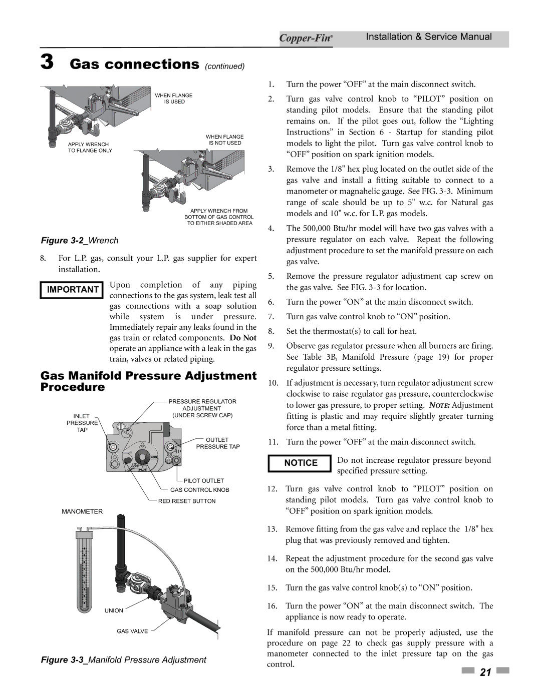
Gas Manifold Pressure Adjustment Procedure
10. If adjustment is necessary, turn regulator adjustment screw |
clockwise to raise regulator gas pressure, counterclockwise |
INLET
PRESSURE
TAP
MANOMETER
PRESSURE REGULATOR
ADJUSTMENT
(UNDER SCREW CAP)
OUTLET
PRESSURE TAP
PILOT OUTLET
GAS CONTROL KNOB
RED RESET BUTTON
to lower gas pressure, to proper setting. NOTE: Adjustment |
fitting is plastic and may require slightly greater turning |
force than a metal fitting. |
11. Turn the power “OFF” at the main disconnect switch. |
NOTICE | Do not increase regulator pressure beyond | |
specified pressure setting. | ||
| ||
|
12. | Turn gas valve control knob to “PILOT” position on |
| standing pilot models. Turn gas valve control knob to |
| “OFF” position on spark ignition models. |
13. | Remove fitting from the gas valve and replace the 1/8" hex |
| plug that was previously removed and tighten. |
14. | Repeat the adjustment procedure for the second gas valve |
| on the 500,000 Btu/hr model. |
15. | Turn the gas valve control knob(s) to “ON” position. |
16. | Turn the power “ON” at the main disconnect switch. The |
UNION
GAS VALVE
Figure 3-3_Manifold Pressure Adjustment
appliance is now ready to operate. |
If manifold pressure can not be properly adjusted, use the procedure on page 22 to check gas supply pressure with a manometer connected to the inlet pressure tap on the gas control.
![]() 21
21 ![]()