Models 90,000 500,000 Btu/hr
Contents
Please read before proceeding
Checking equipment
Codes
Ratings
Copper-fin =B=R Rating
Copper-fin Specifications
Copper-fin How it works
Gas connection pipe
Models CWN270 Front View Model CWN399 Front View
422
Determine unit location
Location of unit
Determine boiler location
3Combustion Air Direct from Outside
6Combustion Air from Outside Single Opening
Minimum Recommended Combustion AIR Supply to Equipment Room
Venting
Conventional Negative Draft Venting System
Vent Pipe Sizes
Venting
Vertical Vent Termination Clearances
Less from Ridge From Parapet Wall
Sidewall Venting
Masonry Chimney Installation
Vent Materials
Number
Automatic Vent Damper
7CB with Vent Damper and Vent Damper Terminal Block
Gas Connection
Gas connections
Gas Supply Gas Pressure Test
Manifold Pressure
Install Piping to Control
Gas Piping
Gas Manifold Pressure Adjustment Procedure
Clockwise to raise regulator gas pressure, counterclockwise
Checking Gas Supply Pressure
4Gas Supply Pressure
Combination Gas Valves
Venting of Combination Gas Valves
Two Stage Burner Control System
Water Flow Switch if equipped
Hydronic piping
Relief Valve
Minimum Required Flow For Heating Boiler
Typical Heating Boiler Installations
Low Water Cutoff if equipped
General Plumbing Rules
System Temperature Rise Chart
Piping of the Boiler System
Water Connections Heating Boilers Only
Heat Exchanger Pressure Drop Chart
Circulator Pump Specifications
Circulator Pump Requirements
Primary/Secondary Boiler Piping
Three Way Valves
Boiler Flow Rates
Primary / Secondary Piping
4Primary / Secondary Piping of a Single Boiler
Not to Exceed 4 Pipe DIA or MAX. of 12 Apart
8Multiple Boilers Zoned with Circulators
Power Venter Connection to Terminal Strip
Terminal Strip Wiring
Boiler Operating Temperature Control
Electrical connections
Temperature Adjustment
Pump Wiring for a Heating Boiler
Operating Temperature Control
Maximum SET Point Determination
Locating Temperature Control
Temperature Control Settings
Maximum Set Point Determination
Multi-Purpose Temperature Sensor
Temperature Control Sensors
Inlet Water Temperature Sensor
Outdoor Air Temperature Sensor
Outdoor Air Reset Option
Installation of a Remote Sensor Boiler Application
Installation of a Tank Sensor Water Heater Application
Additional Temperature Controls
Blocked Vent and Flame Roll-Out / Flame Interlock Switch
Manual Reset High Water Temperature Limit Control
Pre-start Checklist
Start-up
Initial Start-up
Lighting Instructions
1Gas Valve 90,000 270,000 Btu/hr Models
Safety Shutoff Test For Standing Pilot Ignition System
To Turn OFF GAS to Appliance
Operating Instructions
Freeze Protection
Safety Shutoff Test for Spark Ignition Pilot System
Intermittent Pilot Spark Ignition System F9/M9
To Turn Off Gas to Appliance
Water Treatment
Freeze Protection for a Heating Boiler System if required
Domestic water heaters
Required Temperature Rise
Required Temperature Rise
Domestic Water Heaters 90,000 500,000 Btu/hr Models
Water Chemistry
Softened Water Systems
Pump Operation
1Single water heatersingle tank
2Single water heatermultiple tank
3Multiple water heatersingle tank
Minimum Pump Performance
Remote Sensor Installation
Thermostat Settings
Heat Exchanger
5Danger Warning
Thermal Expansion
Water Flow Switch if equipped
Pressure Only Relief Valve
Cathodic Protection
Owner maintenance
Maintenance and annual startup
Service technician
See the User’s Information Manual for instructions
Maintenance
Check Expansion Tank
Check Relief Valve
Combustion Air Adjustment
Check All Wiring
Check Control Settings
Perform Start-up and Checks
Inspect and Clean Burner
Heat Exchanger / Burner Access
Inspection and Cleaning Procedure
Inspection of Heat Exchanger Waterways
Pilot Flame Adjustment Procedure
Clear Area
Water Circulating Pump
Review with owner
Gas Train and Controls
Troubleshooting
Pilot or replace
Wiring Diagram F1 Unit
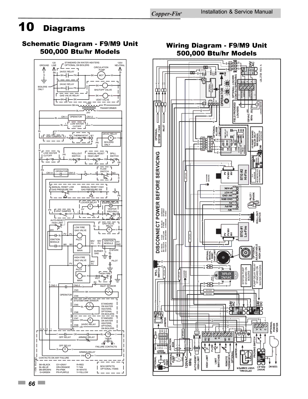
Diagrams
Schematic Diagram F1 Unit
90,000 270,000 Btu/hr Models
Schematic Diagram F9 Unit
Wiring Diagram F9 Unit
315,000 399,999 Btu/hr Models
Diagrams
Diagrams
Page
Revision a ECO #C06290 initial release CFA-I-S Rev a 09/10