Installation & Service Manual
3Gas connections
Checking Gas Supply Pressure
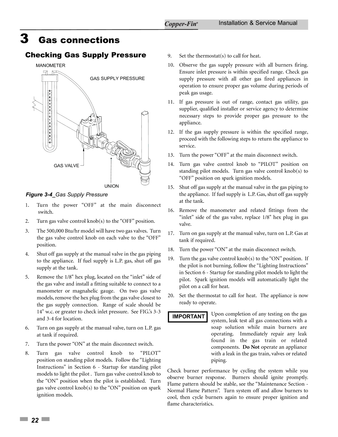
MANOMETER
GAS SUPPLY PRESSURE
GAS VALVE
UNION
Figure 3-4_Gas Supply Pressure
1. | Turn the power “OFF” at the main disconnect |
| switch. |
2. | Turn gas valve control knob(s) to the “OFF” position. |
3. | The 500,000 Btu/hr model will have two gas valves. Turn |
| the gas valve control knob on each valve to the “OFF” |
| position. |
4. | Shut off gas supply at the manual valve in the gas piping |
| to the appliance. If fuel supply is L.P. gas, shut off gas |
| supply at the tank. |
5. | Remove the 1/8" hex plug, located on the “inlet” side of |
| the gas valve and install a fitting suitable to connect to a |
| manometer or magnahelic gauge. On two gas valve |
| models, remove the hex plug from the gas valve closest to |
| the gas supply connection. Range of scale should be |
| 14" w.c. or greater to check inlet pressure. See FIG.’s |
9.Set the thermostat(s) to call for heat.
10.Observe the gas supply pressure with all burners firing. Ensure inlet pressure is within specified range. Check gas supply pressure with all other gas fired appliances in operation to ensure proper gas volume during periods of peak gas usage.
11.If gas pressure is out of range, contact gas utility, gas supplier, qualified installer or service agency to determine necessary steps to provide proper gas pressure to the appliance.
12.If the gas supply pressure is within the specified range, proceed with the following steps to return the appliance to service.
13.Turn the power “OFF” at the main disconnect switch.
14.Turn gas valve control knob to “PILOT” position on standing pilot models. Turn gas valve control knob(s) to “OFF” position on spark ignition models.
15.Shut off gas supply at the manual valve in the gas piping to the appliance. If fuel supply is L.P. Gas, shut off gas supply at the tank.
16.Remove the manometer and related fittings from the “inlet” side of the gas valve, replace 1/8" hex plug in gas valve.
17.Turn on gas supply at the manual valve, turn on L.P. Gas at tank if required.
18.Turn the power “ON” at the main disconnect switch.
19.Turn the gas valve control knob(s) to the “ON” position. If the pilot is not burning, follow the “Lighting Instructions” in Section 6 - Startup for standing pilot models to light the pilot. Spark ignition models will automatically light the pilot on a call for heat.
20.Set the thermostat to call for heat. The appliance is now ready to operate.
| and |
6. | Turn on gas supply at the manual valve, turn on L.P. gas |
| at tank if required. |
7. | Turn the power “ON” at the main disconnect switch. |
8. | Turn gas valve control knob to “PILOT” |
| position on standing pilot models. Follow the “Lighting |
| Instructions” in Section 6 - Startup for standing pilot |
IMPORTANT
Upon completion of any testing on the gas system, leak test all gas connections with a soap solution while main burners are operating. Immediately repair any leak found in the gas train or related components. Do Not operate an appliance with a leak in the gas train, valves or related piping.
models to light the pilot . Turn gas valve control knob to |
the “ON” position when the pilot is established. Turn |
gas valve control knob(s) to the “ON” position on spark |
ignition models.
Check burner performance by cycling the system while you observe burner response. Burners should ignite promptly. Flame pattern should be stable, see the “Maintenance Section - Normal Flame Pattern”. Turn system off and allow burners to cool, then cycle burners again to ensure proper ignition and flame characteristics.
![]() 22
22 ![]()