Installation & Service Manual
5Electrical connections (continued)
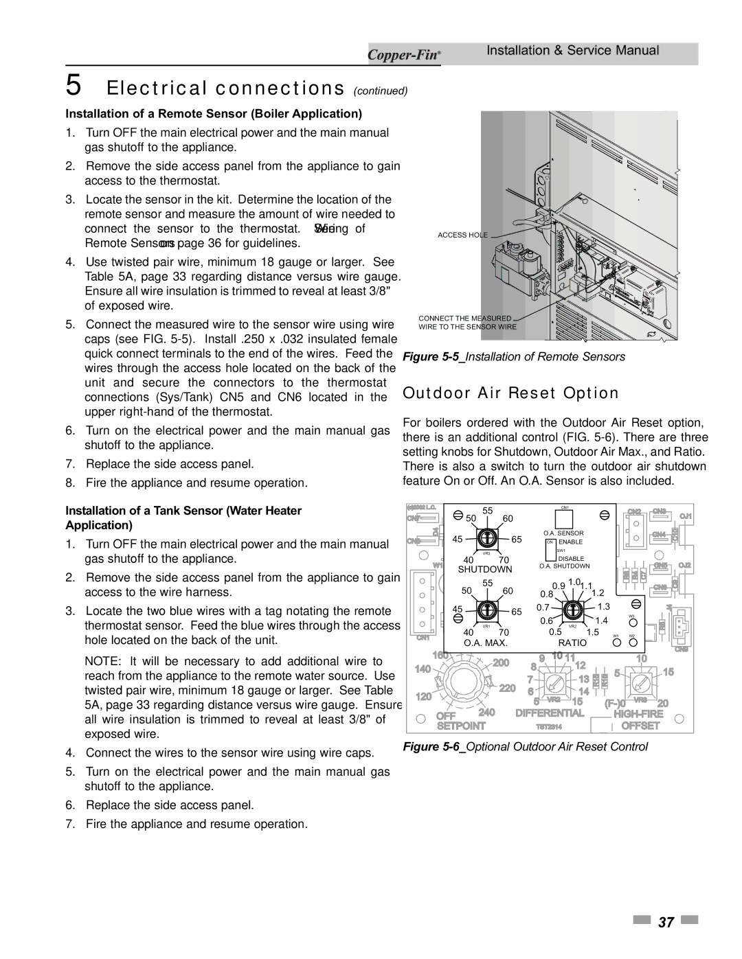
Installation of a Remote Sensor (Boiler Application)
1.Turn OFF the main electrical power and the main manual gas shutoff to the appliance.
2.Remove the side access panel from the appliance to gain access to the thermostat.
3.Locate the sensor in the kit. Determine the location of the remote sensor and measure the amount of wire needed to connect the sensor to the thermostat. See Wiring of Remote Sensors on page 36 for guidelines.
4.Use twisted pair wire, minimum 18 gauge or larger. See Table 5A, page 33 regarding distance versus wire gauge. Ensure all wire insulation is trimmed to reveal at least 3/8" of exposed wire.
5.Connect the measured wire to the sensor wire using wire caps (see FIG.
6.Turn on the electrical power and the main manual gas shutoff to the appliance.
7.Replace the side access panel.
8.Fire the appliance and resume operation.
ACCESS HOLE |
CONNECT THE MEASURED ![]()
![]()
![]()
![]()
WIRE TO THE SENSOR WIRE
Figure 5-5_Installation of Remote Sensors
Outdoor Air Reset Option
For boilers ordered with the Outdoor Air Reset option, there is an additional control (FIG.
Installation of a Tank Sensor (Water Heater Application)
1.Turn OFF the main electrical power and the main manual gas shutoff to the appliance.
2.Remove the side access panel from the appliance to gain access to the wire harness.
3.Locate the two blue wires with a tag notating the remote thermostat sensor. Feed the blue wires through the access hole located on the back of the unit.
NOTE: It will be necessary to add additional wire to reach from the appliance to the remote water source. Use twisted pair wire, minimum 18 gauge or larger. See Table 5A, page 33 regarding distance versus wire gauge. Ensure all wire insulation is trimmed to reveal at least 3/8" of exposed wire.
4.Connect the wires to the sensor wire using wire caps.
5.Turn on the electrical power and the main manual gas shutoff to the appliance.
6.Replace the side access panel.
7.Fire the appliance and resume operation.
(c)2002 L.C. | 55 |
|
| CN1 |
|
| CN2 |
| CN3 |
| |||
|
|
|
|
|
|
|
|
| OJ1 | ||||
CN7 |
| 50 | 60 |
|
|
|
|
|
|
|
|
| |
|
|
|
|
|
|
|
|
|
|
| |||
| D4 |
| 65 | O.A. SENSOR |
|
|
|
|
| CN4 | C10 | ||
CN8 |
|
| ON ENABLE |
|
|
|
|
|
| ||||
45 |
|
|
|
|
|
|
|
| |||||
|
| VR3 |
|
| SW1 |
|
|
|
|
|
|
|
|
|
|
|
|
|
|
|
|
|
|
|
|
| |
|
| 40 | 70 |
| DISABLE |
|
|
|
|
|
|
| |
| W1 | O.A. SHUTDOWN |
|
|
|
|
| CN5 | OJ2 | ||||
| SHUTDOWN |
|
|
|
|
| |||||||
|
|
|
|
|
|
| R6 | R4 | C7 |
|
| ||
|
| 55 |
|
|
| 1.0 |
|
|
| C9 | |||
|
|
|
| 0.9 |
|
|
|
|
| CN6 | |||
|
| 50 | 60 |
| 1.1 |
|
|
|
|
|
| ||
|
| 0.8 | 1.2 |
|
|
|
|
| |||||
|
|
|
|
|
|
|
|
| |||||
| 45 | 65 | 0.7 |
| 1.3 |
|
|
| J4 |
| |||
|
|
|
|
|
|
|
|
| W3 |
|
|
| |
|
|
|
| 0.6 |
| 1.4 |
|
|
|
| |||
|
| VR1 |
| VR2 |
|
|
| R8 |
| ||||
|
|
|
| 0.5 |
|
|
|
|
|
| |||
|
| 40 | 70 |
| 1.5 |
|
|
|
|
| |||
CN1 |
|
|
| W1 | W2 |
|
|
| |||||
| O.A. MAX. |
| RATIO |
|
|
|
|
|
|
| |||
|
|
|
|
|
|
|
|
| CN9 | ||||
| 160 |
|
|
| 10 11 |
|
|
|
|
|
| ||
| 200 | 9 |
|
|
| 10 |
|
| |||||
140 |
| 8 |
| 12 |
|
|
|
|
|
|
| ||
|
|
|
| R15 | R16 | 5 |
|
| 15 | ||||
|
|
|
| 7 |
| 13 |
|
| |||||
|
|
| 220 |
|
|
|
|
|
| ||||
|
|
|
|
|
|
|
|
|
|
| |||
120 |
|
| 6 |
| 14 |
|
|
|
|
|
|
| |
|
|
|
|
|
|
|
|
|
|
| |||
|
|
| 5 | VR2 | 15 |
| VR3 | 20 |
| ||||
|
| 240 |
|
|
| ||||||||
| OFF | DIFFERENTIAL |
|
|
| ||||||||
| SETPOINT |
| TST2314 |
|
|
| OFFSET |
| |||||
Figure 5-6_Optional Outdoor Air Reset Control
![]() 37
37 ![]()