5 specifications
Lochinvar 5 is a cutting-edge residential boiler designed to meet the heating needs of modern homes while ensuring high efficiency and user convenience. As one of the latest offerings from Lochinvar, a trusted name in the heating industry, the Lochinvar 5 combines advanced technology with robust features that make it a top choice for homeowners and contractors alike.One of the standout characteristics of the Lochinvar 5 is its impressive energy efficiency. It boasts an AFUE (Annual Fuel Utilization Efficiency) rating of up to 95%, which significantly reduces fuel consumption compared to traditional heating systems. This not only translates to lower energy bills for homeowners but also minimizes the environmental impact, aligning with the growing demand for sustainable energy solutions.
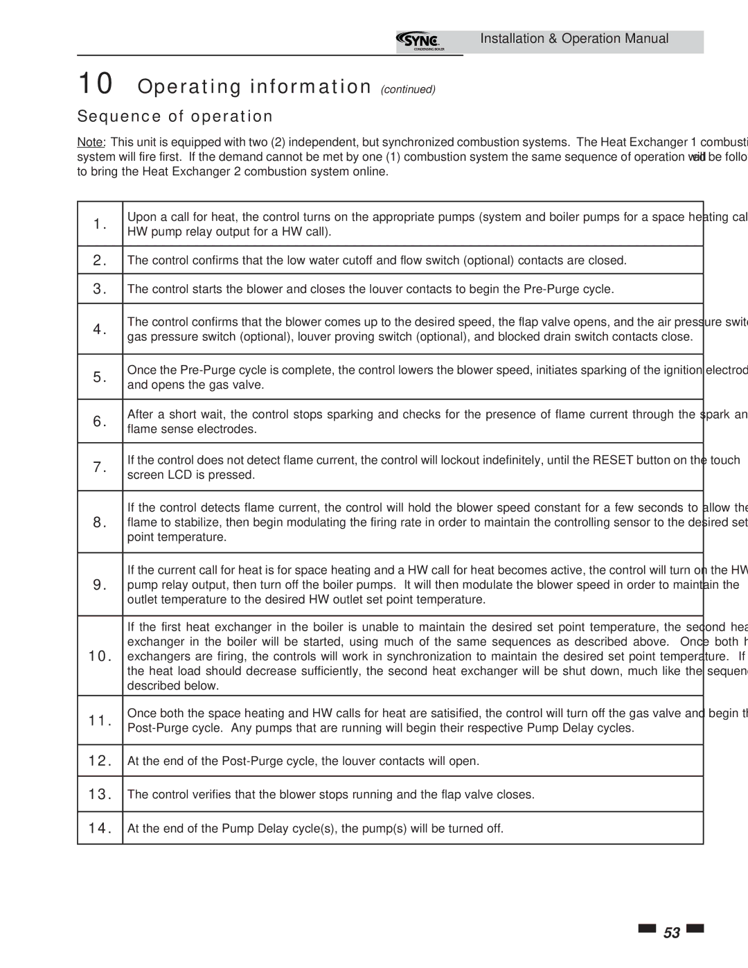
The Lochinvar 5 employs a highly efficient modulating burner technology that optimizes fuel usage based on real-time heating demand. This ensures that the boiler operates at peak efficiency, providing consistent warmth without unnecessary energy waste. The inclusion of advanced controls further enhances its performance, allowing users to adjust settings easily and monitor usage through a user-friendly digital display.
Durability and reliability are also paramount in the design of the Lochinvar 5. Constructed with high-quality materials, this boiler is built to withstand the rigors of daily use and provide long-lasting performance. Its compact design allows for flexible installation options, making it suitable for various residential settings, even where space is limited.
In addition to its impressive performance metrics, Lochinvar 5 is equipped with smart technology features that cater to the needs of modern consumers. Wi-Fi connectivity enables remote monitoring and control via a mobile app, giving homeowners the ability to adjust settings on the go. This feature not only enhances user convenience but also allows for proactive maintenance and alerts, helping to prevent potential issues before they arise.
Safety is a key consideration in the design of Lochinvar 5. It includes multiple safety features, such as a sealed combustion system that minimizes the risk of carbon monoxide leaks and an advanced monitoring system that ensures optimal operating conditions at all times.
In conclusion, the Lochinvar 5 stands out as an exceptional choice for those seeking a reliable, efficient, and smart residential heating solution. Its combination of advanced technologies, user-friendly features, and robust construction make it a leading option in the boiler market, ready to meet the demands of today’s homeowners. With an eye on energy efficiency and ease of use, Lochinvar 5 is well-equipped to provide comfortable, cost-effective heating for years to come.

