Manuals
/
Manitowoc Ice
/
Kitchen Appliance
/
Refrigerator
Manitowoc Ice
11M
manual
2-17, Pre-Chargedrefrigeration Line Requirements, Section, Installation
Models:
11M
1
27
42
42
Download
42 pages
63.4 Kb
24
25
26
27
28
29
30
31
Specification
Install
Connecting Insulated Conduit
Warranty
Dimension
Maintenance
Water Bath Access
Equipment Setup Procedure
Checklist
How to
Page 27
Image 27
Page 26
Page 28
Page 27
Image 27
Page 26
Page 28
Contents
Installation, Use & Care Manual
Model 11M Root Beer System Refrigeration Unit
America’s Quality Choice in Refrigeration
PERSONAL INJURY POTENTIAL
Safety Notices
Procedural Notices
Read These Before Proceeding
Specifications
Table of Contents continued Section
Section Installation
Attention Marine Installations
Connecting Insulated Conduit
Table of Contents continued
Equipment Placement
Tower Installation
Bag-In-BoxSystem Sanitation
Table of Contents continued Section Maintenance
Section Before Calling for Service
Beverage System Cleaning
THIS PAGE INTENTIONALLY LEFT BLANK
Read This Manual
How to Read a Model Number
Section General Information
Section
Special Applications
Accessories
Specifications
ATTENTION MARINE INSTALLATIONS
Serial Plate Location
Warranty Information
General Information
UNPACKING AND INSPECTING
Section Installation
Kit assembly includes
General
Side View
Installation
Dimensions and Clearances
Top View
BLADE TOWER
REMOTE CONDENSER
Safe Installation Dos and Don’ts
REQUIREMENTS FOR POST MIX UNITS
Location Requirements
CLEARANCES
RATINGS
Ambient Location Requirement
Installer Instructions
SPECIFICATIONS
Electrical
GROUNDING INSTRUCTIONS
Drain Hose Connection
Plumbing/Water Supply
PLUMBING POTABLE WATER
PLUMBING REQUIREMENTS - GENERAL
Single Tower Plumbing
PLUMBING CIRCUIT DIAGRAMS - MODEL 11M ROOT BEER
Model 11M Root Beer Dual Tower Plumbing
2-10
Model 11M Root Beer Three Tower Plumbing
2-11
CONNECTING INSULATED CONDUIT
Refrigeration Unit Installation
EQUIPMENT PLACEMENT
TOWER INSTALLATION
Proceed with the Following Tests
CONNECTING SUPPLY LINES
Connecting conduit at the refrigeration unit
2-13
PROPER USE OF JOHN GUEST FITTINGS
Proper John Guest Fitting Installation
Connect the drain
2-14
2-15
Model 11M Connections
Control Switches
INSULATING CONNECTIONS
Condenser and Pre-chargedLines Installation
Aeroquip Connection
2-16
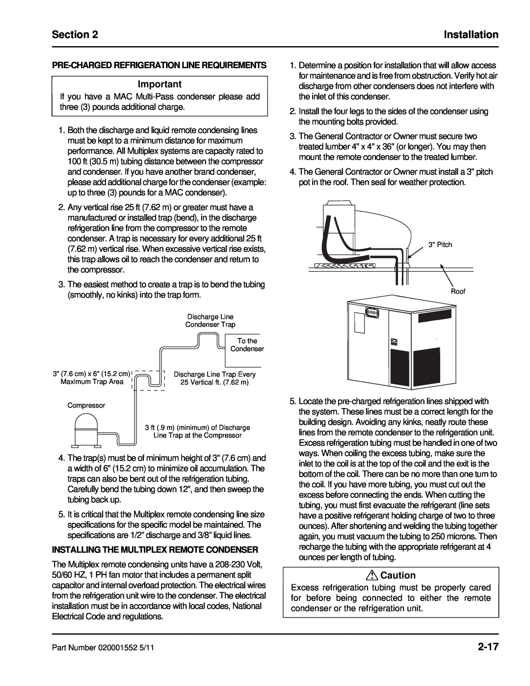
INSTALLING THE MULTIPLEX REMOTE CONDENSER
2-17
PRE-CHARGEDREFRIGERATION LINE REQUIREMENTS
2-18
CONNECTING THE PRE-CHARGED REFRIGERATION LINES
TESTING CO2 CIRCUIT FOR LEAKS
TESTING SYRUP CIRCUIT 5 GALLON TANKS ONLY
BUILDING AN ICE BANK
Start-Up
Preparing Ice Bank
2-19
Check the water bath for full ice bank
Installation Checklist
2-20
Observe the pump operations for leaks
Water Filters
Section Operation
Operation
Typical System
Sequence of Operation
WATER BATH ACCESS
SERVICE ACCESS
How the Multiplex Works
Start-up
Equipment Setup and Close Procedure
EQUIPMENT SETUP PROCEDURE
EQUIPMENT CLOSE PROCEDURE
Operation
Sanitizing
Section Maintenance
Maintenance
BEVERAGE SYSTEM CLEANING
FIGAL BEVERAGE SYSTEM
Shipping, Storage and Relocation
Back-flowPreventer Maintenance
Maintenance
Section Before Calling for Service
Before Calling for Service
Checklist
Before Calling for Service
Section
THIS PAGE INTENTIONALLY LEFT BLANK
Page
Part Number 020001552 5/11
Top
Page
Image
Contents