Model SR7002/SR8002 User Guide
AC Polarized Plug
Read Before Operating Equipment
NEC National Electrical Code
Remote Controller RC8001SR
Accessories Check
Introduction
User Guide
Features
Table of Contents
Hdcd
Copyright Protection
Description
Dts Digital Surround
THX Select2
Dts Neo6
Dts Digital Surround ES
About Dolby Pro Logic
Before USE
Remote Control
Operation of Remote Controller
Battery Replacement Interval RC8001SR
Loading Batteries
Front Panel
Names and Function
AUDIO/ Video
FL Display and Indicater
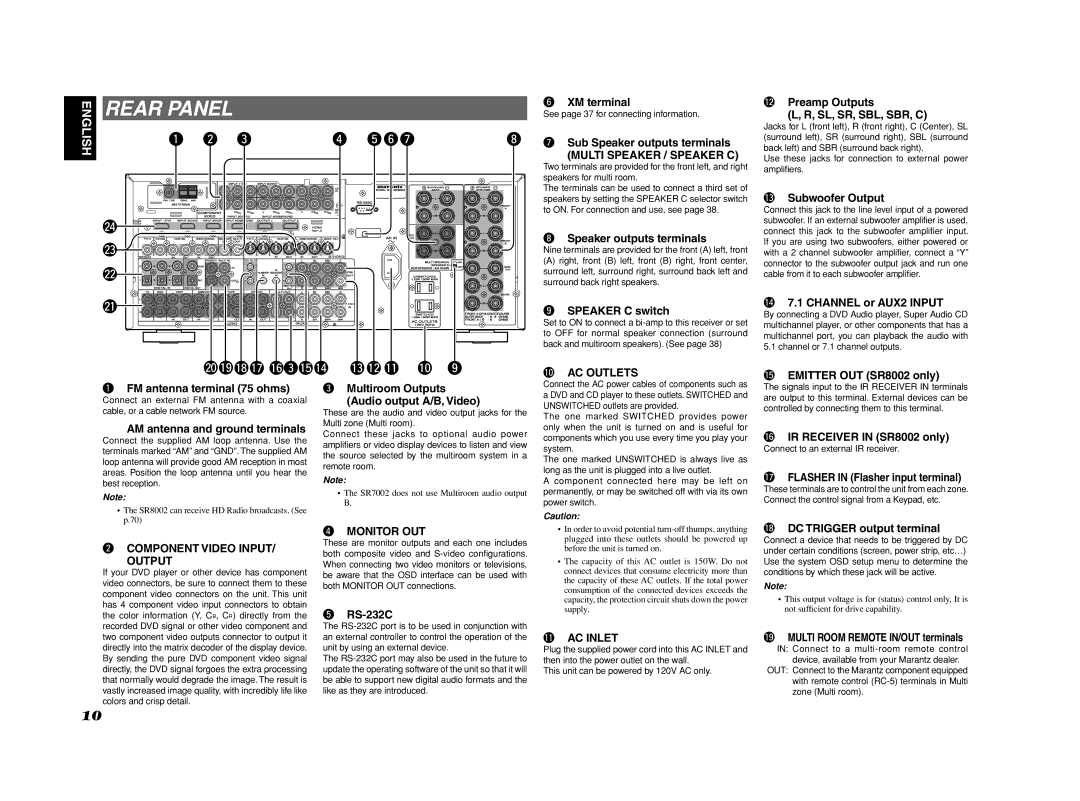
Multi Speaker / Speaker C
Rear Panel
0AC Outlets
Output
@1AUDIO IN/OUT TV, DVD, VCR1, DSS/VCR2, TAPE, CD/CDR
Remote Control
@3VIDEO IN/OUT TV, DVD, VCR1, DSS/VCR2
@4HDMI Input / Output
LCD Indicators RC8001SR
Tuner Mode
Setting the Time
General Information of RC8001SR to the Unit
Checking the Time
Stop
Controlling Marantz Components
Pause
Call up the menu
Turns the VCR on and off
Exits the programming menu
Record
Dock connector OFF
Dock connector on
Turns the Tape deck on
Turns the Tape deck off
Preset Mode
USE Mode
Entering and Setting the Manufacturer Number Di- rectly
Setting Equipment Not Appearing in Manufacturer Number List
Programming the 2 Play and Other Control But
When OK
Tons and Numeric Buttons
Programming the Direct Buttons and Rewriting Names
Erasing Buttons and Erasing Direct Buttons
Erasing Programmed Codes Returning to Initial Settings
Erasing Direct Button Pages
Erasing Sources
Erasing All
Programming Macros
Programming Macros
Executing Macro Programs
Inserting Steps in Macro Programs
When clearing macros, the macros programmed to
Erasing Steps of Macro Programs
Overwriting Steps in Macro Programs
Clone Mode
Setting the Lighting Time
Setup
Setting the Macro Interval Time
Adjusting the Display Contrast
⁄2 DISC+/T.MODE
Operation RC101
Controlling a Marantz TV TV
General Information of RC101 to the Unit
Zone a Multi room a control Zone B Multi room B control
Zone D Main room control
Controlling a Marantz Satellite Broadcasting Tuner DSS
Controlling a Marantz VCR Deck VCR1/ VCR2
Controlling a Marantz Tuner T1
Controlling a Marantz DVD Player DVD
Enter 3CURSOR 4CURSOR 2CURSOR 1CURSOR
Controlling a Marantz Universal Dock AUX1
Setting the Back Light
Normal Mode
Resetting the Code
Programming with the 4-DIGIT Code
Learning Procedure
Learn Mode
Creating copies using clone mode
Change the Multi Room Control Commands for Each Zone
Copying entire contents
Other Operations
Connecting Speakers
Speaker Placement
Connecting Speaker Wire
Connections
Connecting a Subwoofer
Connecting Audio Components
VIDEO, S-VIDEO, Component Jacks
Connecting Video Components
Video jack
Component jack
Connecting Hdmi Components
Connecting Hdmi Components
Hdmi Jack
Connecting Multi Channel Audio Source
Advanced Connecting
Connecting AN External Power Amplifier
Connecting the Antenna Terminals
How to Subscribe
Connecting the XM CONNECT-AND-PLAY Antenna
See the Checking the XM Signal Strength and Radio ID
XM Radio Overview
Connecting for Speaker C USE
Connecting for the Multi Room
Multiroom B
Multiroom a
DC OUT DC Trigger
Connecting Other Equipment
Emitter OUT SR8002 Only
Flasher
Onscreen Display Menu System
Setup
Surround Setup P
Input Setup P
Speaker Setup P
SUB Menu
Func Input Setup
Input Setup
CH Input Setup
Func Rename
7.1 CH Input Setup
Func Input Setup Assignable Digital Input
Function Rename
Default
Back
Space
Auto Setup
Spkr Speaker Setup
Manual Setup
THX Audio Setup
Unit measures sound characteristics
Auto Setup MultEQ Setup feature
Automatically optimizes settings
To do this, the Auto Setup feature measures a
OK/ENTER button
Example Confirmation screen for speaker detection
Cause How to Remedy
Error Messages
Speaker Size
Manual Setup
Speaker Distance
Speaker Level
THX Audio Setup
Advanced Speaker Array ASA
Speaker type and positioning
Channel Level
Surround Setup
Csiiparameter
PLIIx PRO Logic IIx Music Parameter
NEO6 Parameter
Video Convert
Video Setup
Preference
DC Trigger Setup
Multi Room Setup
Acoustic EQ
Reset
Preset G. EQ ADJ
Check Auto
Frequency
Using the unit
Selecting the Surround Mode
Using the remote controller
Dialogue Normalization Message
Using the Sleep Timer
Adjusting the Tone Bass & Treble Control
Video Convert
For setting instructions, see
Surround Mode
Convert
SBR
Source Direct
Auto
Pure Direct
EX/ES
THX Games
Stereo
Multi CH. MOVIE, Music
THX Cinema
Recording AN Analog Source
Listening Through Headphones
Selecting Analog Audio Input or Digital Audio Input
Attenuation to Analog Input Signal
Dolby Headphone Mode
Speaker A/B
CH Input
AUX2 Input
Dual Backup Memory
Video ON/OFF
LIP.SYNC
Manual Tuning
Auto Tuning
Basic Operation
Listening to the Tuner
FM Tuning Mode Auto Stereo or Mono
Preset Memory
Auto Preset Memory
Manual Preset Memory
Preset Channel List Display
Recalling a Preset Station
Sorting Preset Stations
Clearing Stored Preset Stations
For Listening to HD Radio Stations SR8002 only
Analog/Digital Auto Mode
Than 2 seconds
→ B → C ... Z → 1 → 2 → 3 .... → → + → / → Blank → a UP →
Switching HD-RADIO Information Inthe Front
HD Radio Auto Tuning
Signal Strong
Using the SR8002
PTY Auto Search
Selecting Multicast Channels
Multicast Channels
Press the SCAN+ D1 or SCAN- D2 button
Rbds Operation SR8002 only
When the Text 1 Radio Text is displayed
Radio Text
Rbds Display
Signal Marginal
Switching XM Information in the Front Panel Display
Signal NON
Listening to XM Satellite Radio
Preset Search Mode
Search Mode
ALL Channel Search Mode
When the Artist name/Song title is displayed
Memory
You can store the desired channel in the Preset
FM/AM stations
Tune into the desired channel
Neural Surround Mode
Multi Room System
Multi Room Playback Using the Multi
Room OUT Terminals
Speaker Terminals
Tuner mode operation remote code Refer to
Power ON/OFF
RC101 for Multiroom a
RC101 for Multiroom B
Symptom Cause Remedy
Troubleshooting
Speaker
Hdmi
Symptom Cause Remedy
XM Satellite Radio
HD Radio Reception
HOW to Reset the Unit
Accessories
Dimensions
Front KEY Button Lock of the Unit
Amplifier
Setup Codes
RECEIVER/TUNER
RECEIVER/TUNER Cable Satellite
Laser Disk
Tape Deck CD/CD-R Player
Iii
Source button name TV Source button name VCR
VCR
Source button name VCR Source button name DVD
VCR DVD
Direct Button
1002, 1009
1141
1059
1117
DSS
Is a registered trademark