| Connector pinouts for Matrox | 47 | ||
|
|
|
| |
Medium Configuration |
|
|
| |
|
|
|
|
|
Pin | Signal | Pin | Signal |
|
|
|
|
|
|
8 | DATA, INPUT, Y3+ | 21 | DATA, INPUT, Y3- |
|
|
|
|
|
|
9 | CLOCK, INPUT , Y+ | 22 | CLOCK, INPUT , Y- |
|
|
|
|
|
|
10 | DATA, INPUT, Y2+ | 23 | DATA, INPUT, Y2- |
|
|
|
|
|
|
11 | DATA, INPUT, Y1+ | 24 | DATA, INPUT, Y1- |
|
|
|
|
|
|
12 | DATA, INPUT, Y0+ | 25 | DATA, INPUT, Y0- |
|
|
|
|
|
|
13 | INNER SHIELD | 26 | INNER SHIELD |
|
|
|
|
|
|
Use the Camera Link cable from your camera manufacturer or from 3M Interconnect Solutions for Factory Automation, to interface with the above connectors. Note that this cable is not available from Matrox.
| • | Manufacturer: | 3M Interconnect Solutions for Factory Automation |
| • | Camera Link cable part number: | |
Caution | If using the two Camera Link connectors, the cables you choose should be of the | ||
| same type and length. |
| |
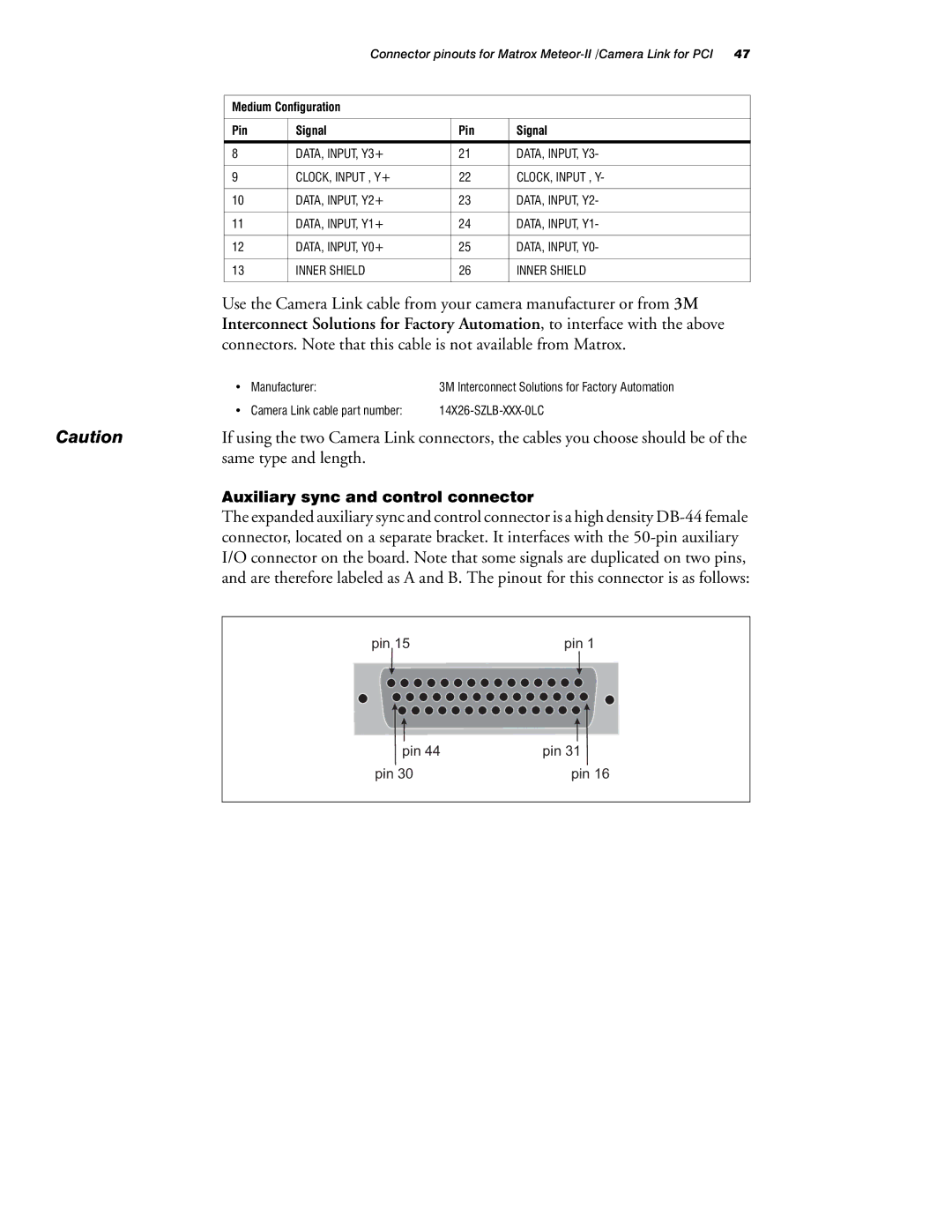
Auxiliary sync and control connector
The expanded auxiliary sync and control connector is a high density
pin 15 | pin 1 |
pin 44 | pin 31 |
pin 30 | pin 16 |