18Chapter 2: Hardware installation
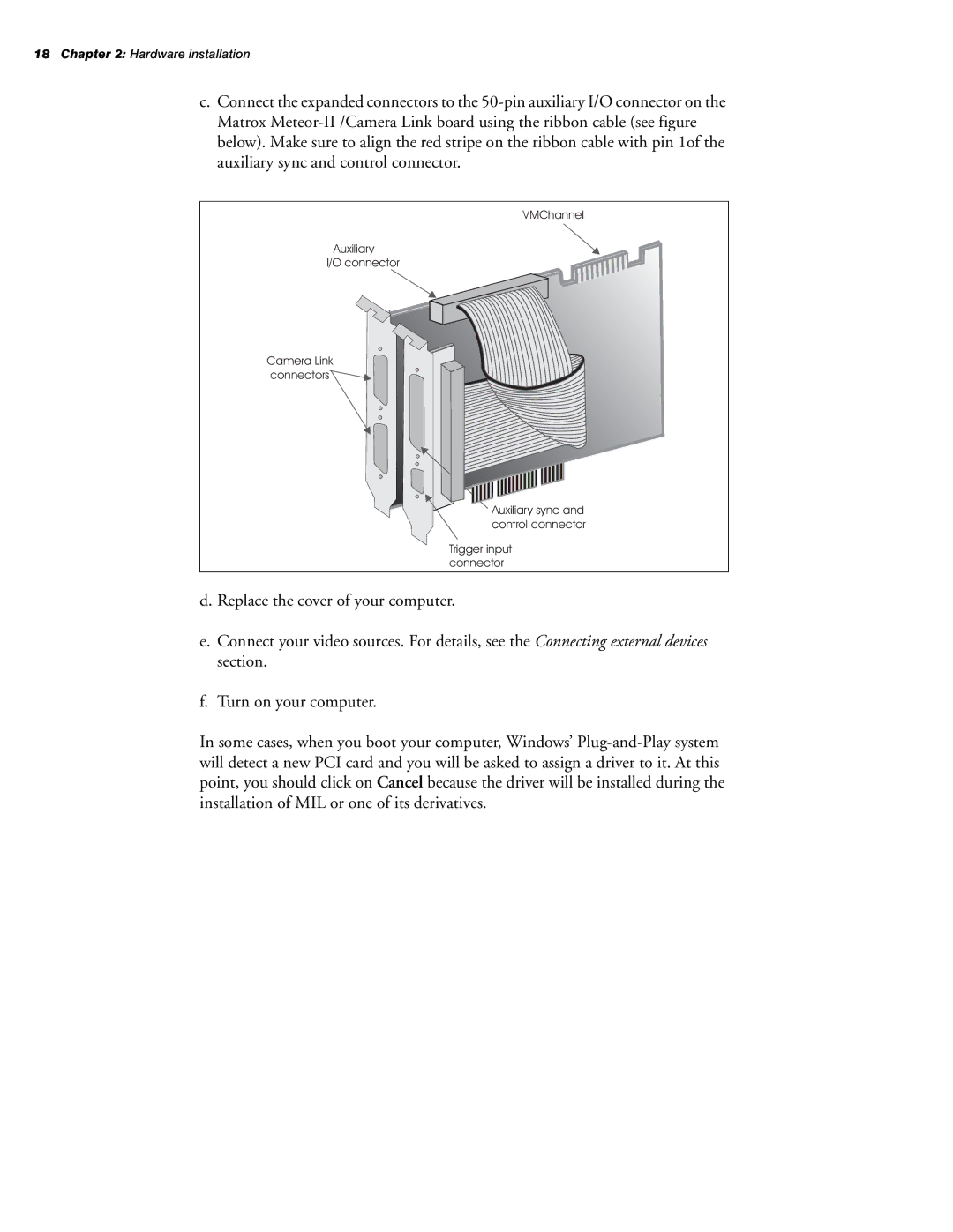
c.Connect the expanded connectors to the 50-pin auxiliary I/O connector on the Matrox Meteor-II /Camera Link board using the ribbon cable (see figure below). Make sure to align the red stripe on the ribbon cable with pin 1of the auxiliary sync and control connector.
VMChannel
Auxiliary
I/O connector
Camera Link connectors
Auxiliary sync and control connector
Trigger input connector
d. Replace the cover of your computer.
e.Connect your video sources. For details, see the Connecting external devices section.
f.Turn on your computer.
In some cases, when you boot your computer, Windows’ Plug-and-Play system will detect a new PCI card and you will be asked to assign a driver to it. At this point, you should click on Cancel because the driver will be installed during the installation of MIL or one of its derivatives.