32Chapter 5: Hardware reference
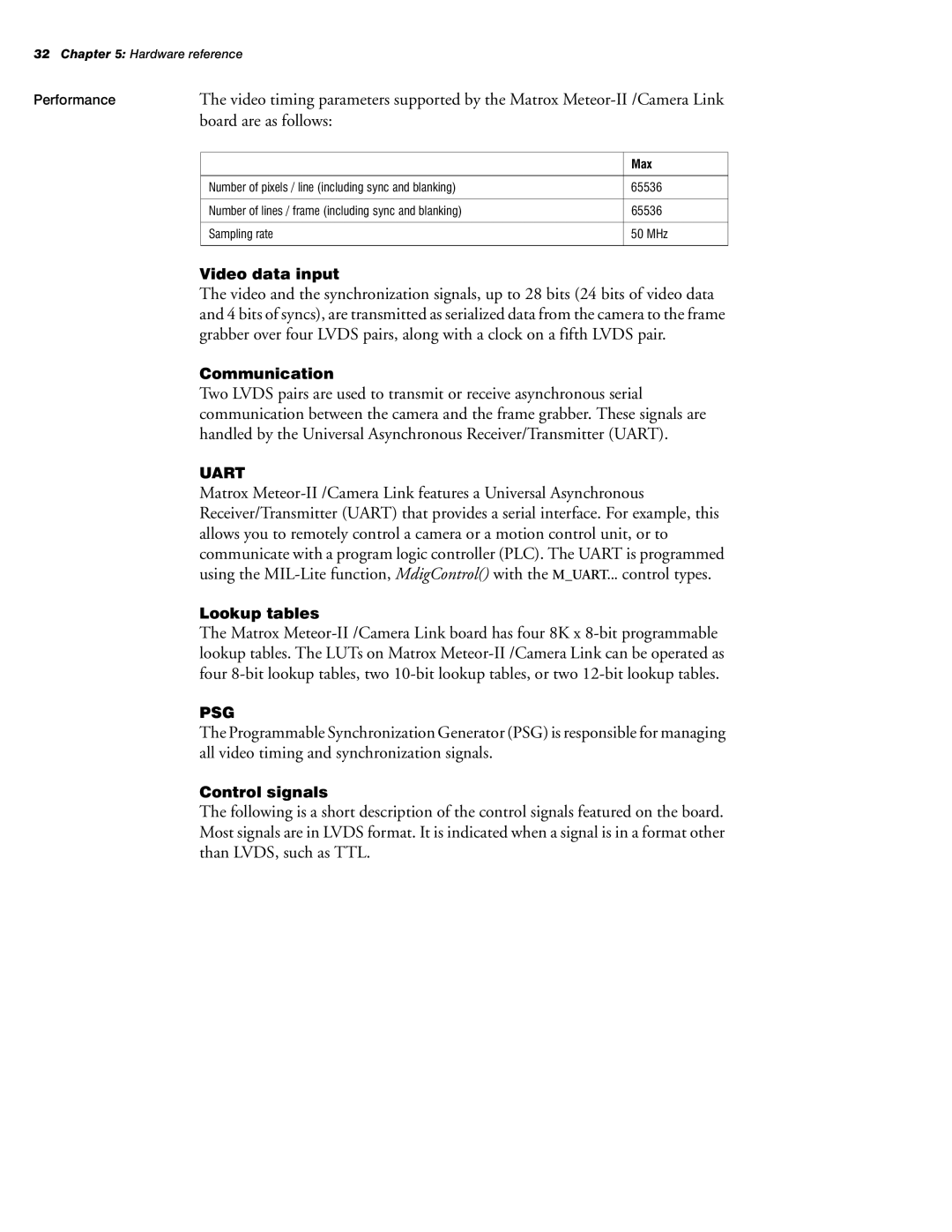
Performance | The video timing parameters supported by the Matrox | |
| board are as follows: |
|
|
|
|
|
| Max |
|
|
|
| Number of pixels / line (including sync and blanking) | 65536 |
|
|
|
| Number of lines / frame (including sync and blanking) | 65536 |
|
|
|
| Sampling rate | 50 MHz |
|
|
|
Video data input
The video and the synchronization signals, up to 28 bits (24 bits of video data and 4 bits of syncs), are transmitted as serialized data from the camera to the frame grabber over four LVDS pairs, along with a clock on a fifth LVDS pair.
Communication
Two LVDS pairs are used to transmit or receive asynchronous serial communication between the camera and the frame grabber. These signals are handled by the Universal Asynchronous Receiver/Transmitter (UART).
UART
Matrox
Lookup tables
The Matrox
PSG
The Programmable Synchronization Generator (PSG) is responsible for managing all video timing and synchronization signals.
Control signals
The following is a short description of the control signals featured on the board. Most signals are in LVDS format. It is indicated when a signal is in a format other than LVDS, such as TTL.