52Appendix B: Technical information
Connector pinouts for Matrox
Matrox
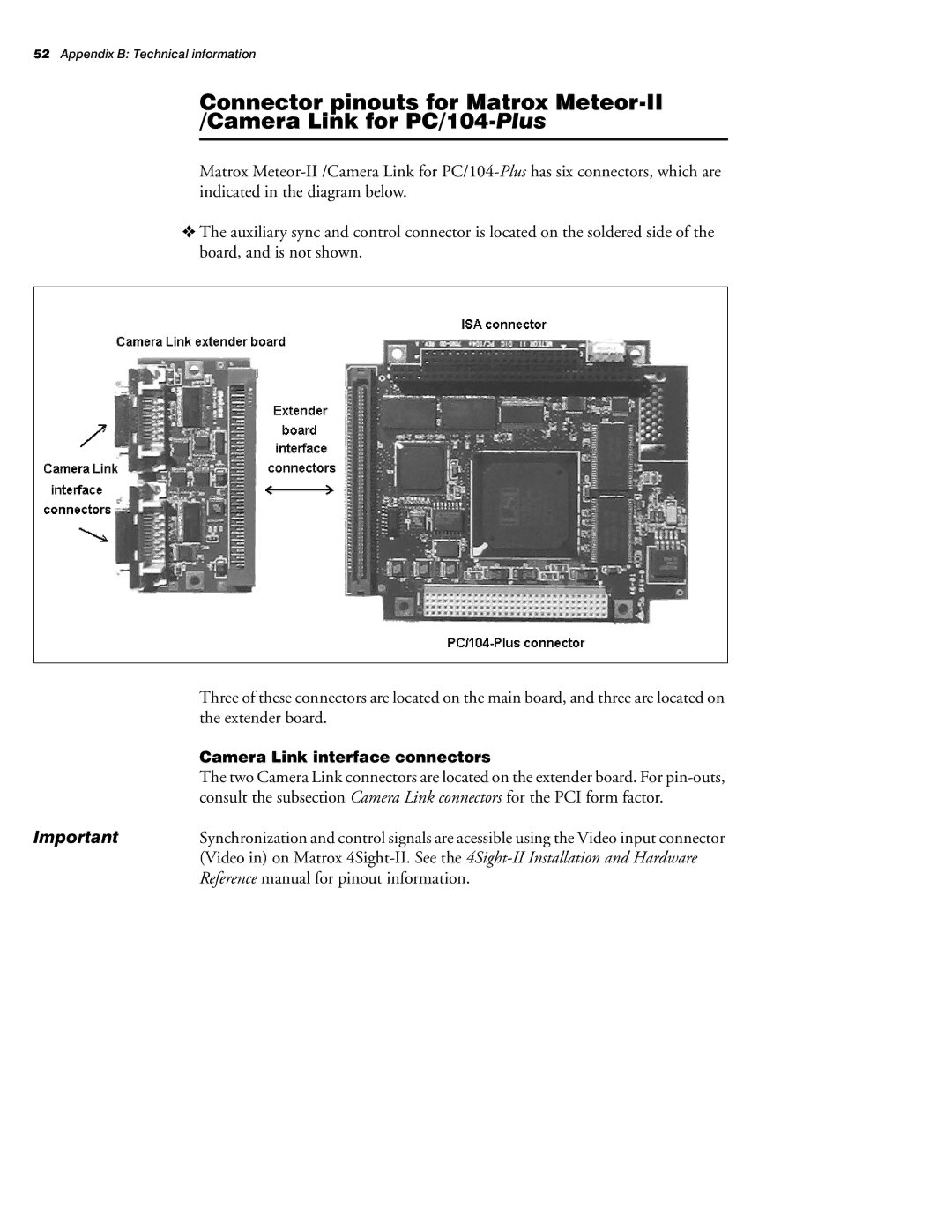
✁The auxiliary sync and control connector is located on the soldered side of the board, and is not shown.
| Three of these connectors are located on the main board, and three are located on |
| the extender board. |
| Camera Link interface connectors |
| The two Camera Link connectors are located on the extender board. For |
| consult the subsection Camera Link connectors for the PCI form factor. |
Important | Synchronization and control signals are acessible using the Video input connector |
| (Video in) on Matrox |
| Reference manual for pinout information. |