Pulsar MX
1.2 Rear Panels
Pulsar MX 5000 RT | Pulsar MX EXB RT | Transformer 5000 |
2 |
|
| 200 |
|
|
| |
3 |
|
|
|
4 |
|
|
|
180VDdc | CONNECTOR | BATTERY |
|
UNDER LOAD | BATTERY CABLE | CAUTION: DO NOT DISCONNECT |
|
6 |
|
|
|
7 |
| BATT. NO. RPO | |
|
|
|
1 12
5 | 11 |
8
9
10
13
12
LOAD 4 BREAKER | LOAD 3 BREAKER |
LOAD 4 | LOAD 3 / |
/ 120V~,16A | 120V~,16A |
BREAKER | LOAD 2 |
| LOAD 1 BREAKER |
120V~,16A | LOAD 1 |
|
|
120V~,16A | LOAD 2 |
|
|
208~ | 240~ | INPUT VOLTAGE SELECTION | SET THIS SWITCH WHEN UNPOWERED BY ALL SOURCES |
BREAKER | INPUT |
PROTECTION | TRANSFORMER |
14
15
16
17
19
18
63
64
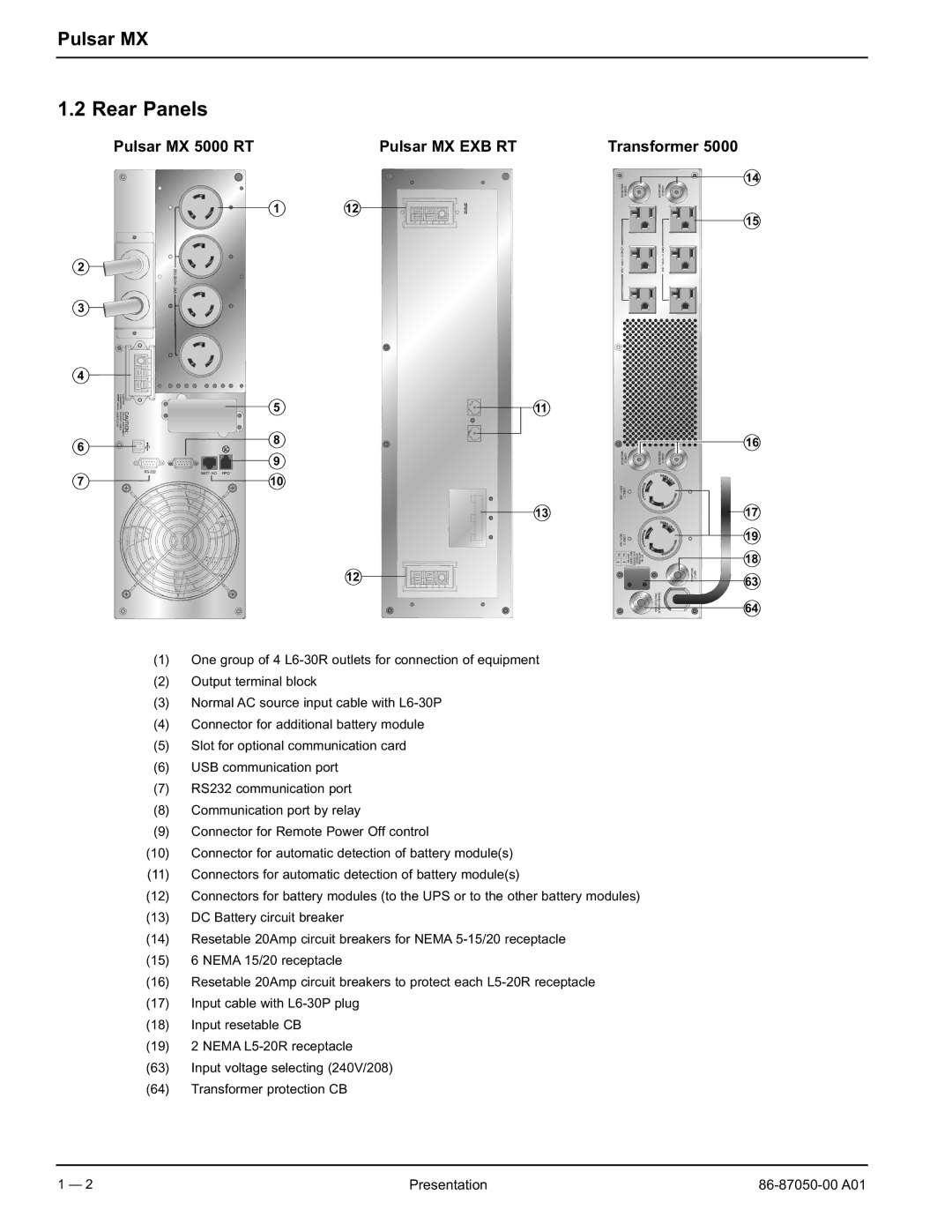
(1)One group of 4
(2)Output terminal block
(3)Normal AC source input cable with
(4)Connector for additional battery module
(5)Slot for optional communication card
(6)USB communication port
(7)RS232 communication port
(8)Communication port by relay
(9)Connector for Remote Power Off control
(10)Connector for automatic detection of battery module(s)
(11)Connectors for automatic detection of battery module(s)
(12)Connectors for battery modules (to the UPS or to the other battery modules)
(13)DC Battery circuit breaker
(14)Resetable 20Amp circuit breakers for NEMA
(15)6 NEMA 15/20 receptacle
(16)Resetable 20Amp circuit breakers to protect each
(17)Input cable with
(18)Input resetable CB
(19)2 NEMA
(63)Input voltage selecting (240V/208)
(64)Transformer protection CB
1 — 2 | Presentation |
