MicroNet Technology SP5100 user manual

Models: SP5100

1 58
Download 58 pages 54.63 Kb
Page 8
Image 8

Note:

All function keys mentioned above (except Number 1
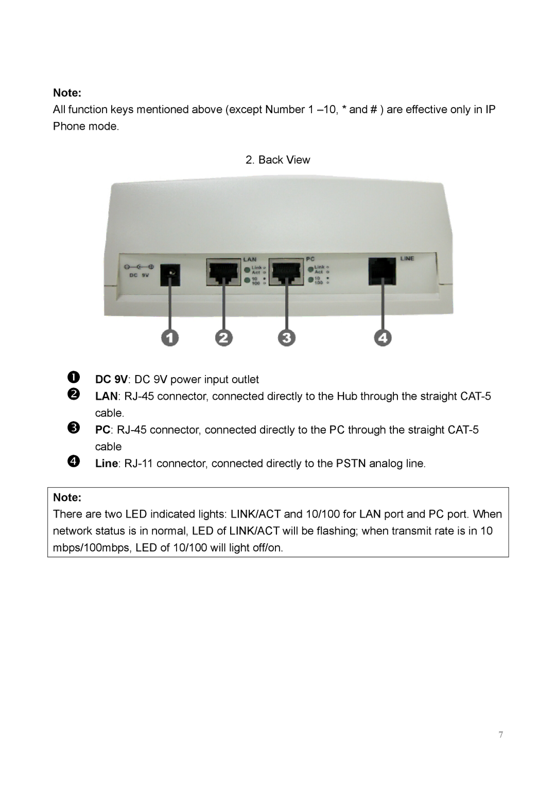
 –10, * and # ) are effective only in IP Phone mode.

2. Back View

n o

p

q

DC 9V: DC 9V power input outlet

LAN: RJ-45 connector, connected directly to the Hub through the straight CAT-5 cable.

PC: RJ-45 connector, connected directly to the PC through the straight CAT-5 cable

Line: RJ-11 connector, connected directly to the PSTN analog line.

Note:

There are two LED indicated lights: LINK/ACT and 10/100 for LAN port and PC port. When network status is in normal, LED of LINK/ACT will be flashing; when transmit rate is in 10 mbps/100mbps, LED of 10/100 will light off/on.

7

Page 8
Image 8
MicroNet Technology SP5100 user manual