| Hardware Installation |
2.5.4. CPU Fan and Chassis Fan Connectors | |
Connector: | CN13 (FAN1)/CN17 (FAN2) |
Type: | 3 pin |
The cooling fans must be connected to their respective power connectors. If you have installed the
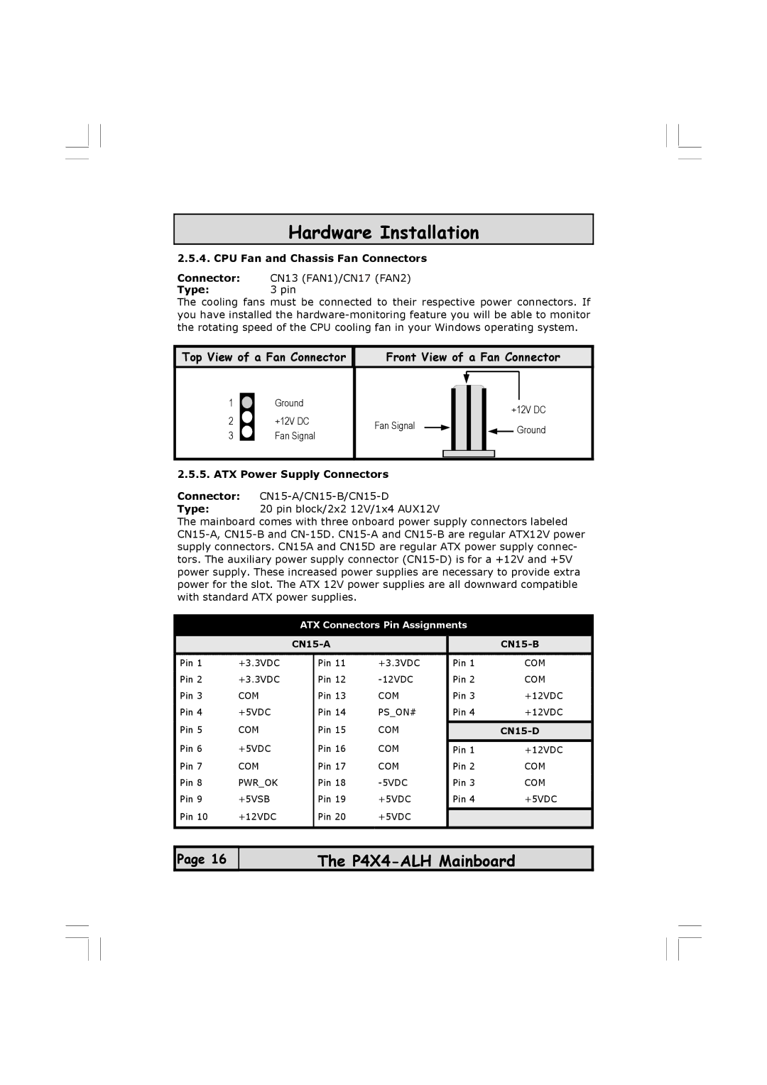
Top View of a Fan Connector | Front View of a Fan Connector | |||
1 | Ground |
| +12V DC | |
2 | +12V DC |
| ||
Fan Signal | Ground | |||
3 | Fan Signal | |||
| ||||
|
| |||
2.5.5. ATX Power Supply Connectors |
| |||
Connector: |
| |||
Type: | 20 pin block/2x2 12V/1x4 AUX12V |
| ||
The mainboard comes with three onboard power supply connectors labeled
ATX Connectors Pin Assignments
|
|
|
| |||
Pin 1 | +3.3VDC |
| Pin 11 | +3.3VDC | Pin 1 | COM |
Pin 2 | +3.3VDC |
| Pin 12 | Pin 2 | COM | |
Pin 3 | COM |
| Pin 13 | COM | Pin 3 | +12VDC |
Pin 4 | +5VDC |
| Pin 14 | PS_ON# | Pin 4 | +12VDC |
Pin 5 | COM |
| Pin 15 | COM |
|
|
|
|
| ||||
Pin 6 | +5VDC |
| Pin 16 | COM | Pin 1 | +12VDC |
Pin 7 | COM |
| Pin 17 | COM | Pin 2 | COM |
Pin 8 | PWR_OK |
| Pin 18 | Pin 3 | COM | |
Pin 9 | +5VSB |
| Pin 19 | +5VDC | Pin 4 | +5VDC |
Pin 10 | +12VDC |
| Pin 20 | +5VDC |
|
|
|
|
| ||||
|
|
|
|
|
|
|
![]() Page 16
Page 16
The