.A complete Parts List is available at www.MillerWelds.com
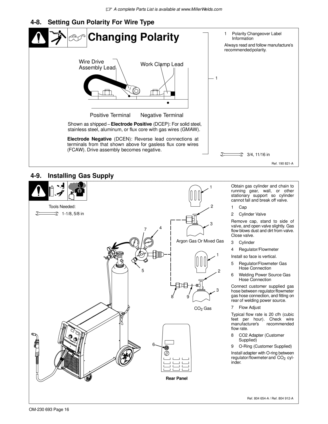
4-8. Setting Gun Polarity For Wire Type


 Changing Polarity
Wire Drive | Work Clamp Lead | |
Assembly Lead | ||
|
D
D
+Positive Terminal - Negative Terminal
Shown as shipped − Electrode Positive (DCEP): For solid steel, stainless steel, aluminum, or flux core with gas wires (GMAW).
Electrode Negative (DCEN): Reverse lead connections at terminals from that shown above for gasless flux core wires (FCAW). Drive assembly becomes negative.
1Polarity Changeover Label Information
Always read and follow manufacture’s recommended polarity.
1
3/4, 11/16 in
Ref. 190
4-9. Installing Gas Supply
|
| 1 |
Tools Needed: |
| 2 |
|
| |
| 4 | 3 |
7 |
| |
|
| |
|
| Argon Gas Or Mixed Gas |
|
| 1 |
5 |
| 2 |
|
| 3 |
| 8 | 9 |
CO2 Gas
6
Obtain gas cylinder and chain to running gear, wall, or other stationary support so cylinder cannot fall and break off valve.
1Cap
2Cylinder Valve
Remove cap, stand to side of valve, and open valve slightly. Gas flow blows dust and dirt from valve. Close valve.
3Cylinder
4Regulator/Flowmeter
Install so face is vertical.
5Regulator/Flowmeter Gas Hose Connection
6Welding Power Source Gas Hose Connection
Connect customer supplied gas hose between regulator/flowmeter gas hose connection, and fitting on rear of welding power source.
7 Flow Adjust
Typical flow rate is 20 cfh (cubic feet per hour). Check wire manufacturer’s recommended flow rate.
8CO2 Adapter (Customer Supplied)
9
Install adapter with
Rear Panel
Ref. 804