.A complete Parts List is available at www.MillerWelds.com
4-13. Selecting A Location And Connecting Input Power
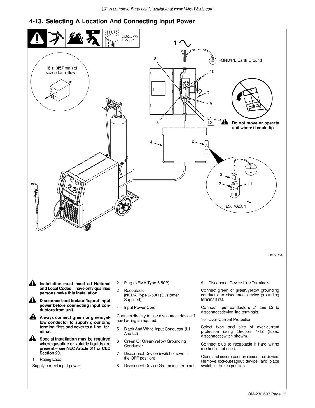
18 in (457 mm) of space for airflow
1 ![]()
8 | =GND/PE Earth Ground |
| |
| 10 |
| 7 |
|
|
|
| 9 |
|
|
|
6 | L1 | 5 | ! |
|
L2 | Do not move or operate | |||
|
|
|
| unit where it could tip. |
42
1
3
L2L1
230 VAC, 1
804
![]() ! Installation must meet all National and Local Codes − have only qualified persons make this installation.
! Installation must meet all National and Local Codes − have only qualified persons make this installation.
![]() ! Disconnect and lockout/tagout input power before connecting input con- ductors from unit.
! Disconnect and lockout/tagout input power before connecting input con- ductors from unit.
!Always connect green or green/yel-
low conductor to supply grounding terminal first, and never to a line ter- minal.
!Special installation may be required where gasoline or volatile liquids are present − see NEC Article 511 or CEC Section 20.
1 Rating Label
Supply correct input power.
2Plug (NEMA Type
3Receptacle
[NEMA Type
4Input Power Cord.
Connect directly to line disconnect device if hard wiring is required.
5Black And White Input Conductor (L1 And L2)
6Green Or Green/Yellow Grounding Conductor
7Disconnect Device (switch shown in the OFF position)
8Disconnect Device Grounding Terminal
9 Disconnect Device Line Terminals
Connect green or green/yellow grounding conductor to disconnect device grounding terminal first.
Connect input conductors L1 and L2 to disconnect device line terminals.
10
Select type and size of
Connect plug to receptacle if hard wiring method is not used.
Close and secure door on disconnect device. Remove lockout/tagout device, and place switch in the On position.