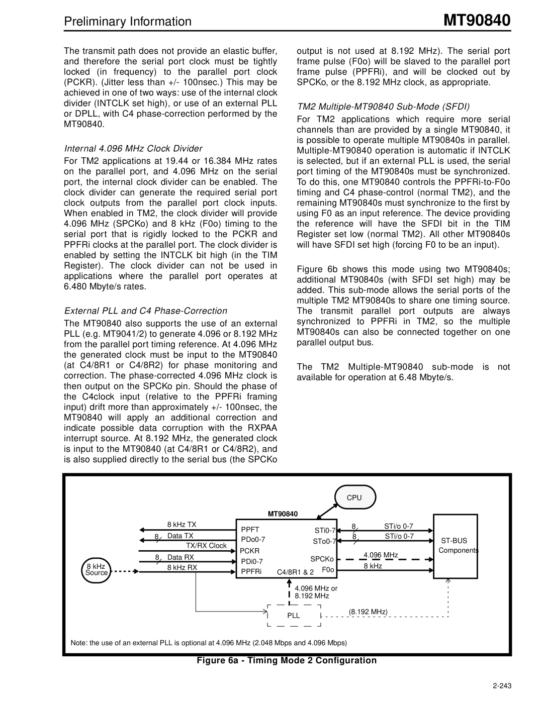
MT90840 specifications
The Mitel MT90840 is an advanced telecommunications device designed to enhance connectivity and communication capabilities for various applications. With its robust array of features and technologies, the MT90840 is well-suited for businesses looking to improve their communications infrastructure.One of the standout features of the Mitel MT90840 is its integration of voice and data services. This allows users to manage their communications more efficiently, streamlining operations and reducing costs. The device supports a wide range of voice codecs, ensuring high-quality audio during calls and providing flexibility for users who may require different standards for different applications.
Another key characteristic of the MT90840 is its scalability. The device is designed to grow with the needs of a business. It supports multiple lines and can be configured to handle an increasing number of users without compromising performance. This scalability is particularly advantageous for organizations that may undergo growth or changes in their communication needs over time.
The Mitel MT90840 also incorporates advanced networking technologies, such as VoIP (Voice over Internet Protocol). This allows users to make voice calls using the internet rather than traditional phone lines, reducing costs for long-distance calls and improving overall communication efficiency. The device is equipped with features that support secure, encrypted communication, further protecting sensitive data and conversations from potential breaches.
Additionally, the MT90840 is designed with user-friendliness in mind. It features an intuitive interface that simplifies operation, making it accessible even for those who may not be tech-savvy. The device is compatible with various peripherals, such as headsets and conferencing equipment, further enhancing its usability in diverse settings, from small offices to large conference rooms.
Moreover, the Mitel MT90840 offers excellent interoperability with a variety of third-party applications. This flexibility enables organizations to integrate the device into their existing systems seamlessly, thereby enhancing productivity without requiring a complete technological overhaul.
In conclusion, the Mitel MT90840 stands out as a versatile and reliable telecommunications solution. Its rich feature set, including voice and data integration, scalability, VoIP capabilities, user-friendly interface, and interoperability, makes it an ideal choice for businesses looking to elevate their communications strategy.

