MITSUBISHI | 9800A SERIES UPS | Page Number: |
ELECTRIC | OWNERS / TECHNICAL MANUAL |
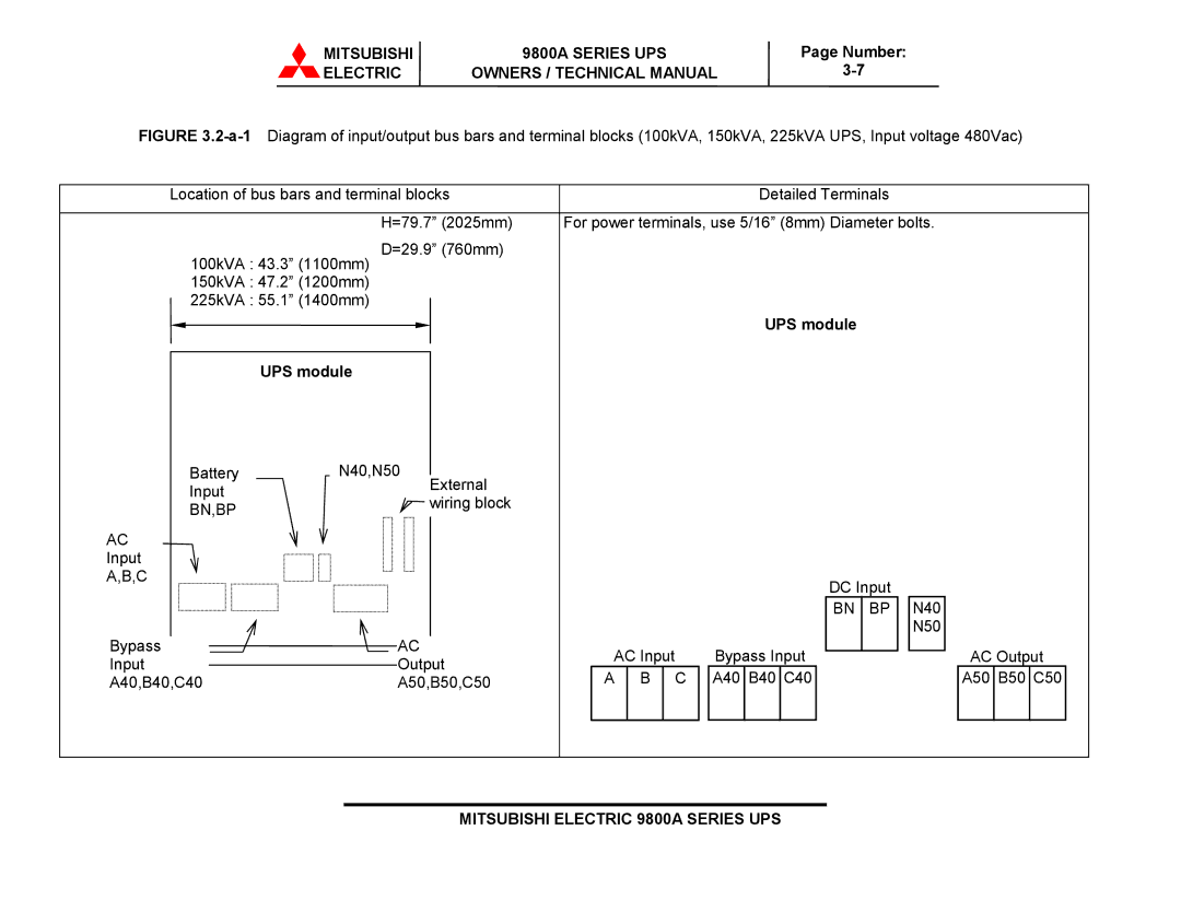
FIGURE 3.2-a-1 Diagram of input/output bus bars and terminal blocks (100kVA, 150kVA, 225kVA UPS, Input voltage 480Vac)
Location of bus bars and terminal blocks |
|
|
| Detailed Terminals |
| ||
| H=79.7” (2025mm) | For power terminals, use 5/16” (8mm) Diameter bolts. | |||||
| D=29.9” (760mm) |
|
|
|
|
|
|
100kVA : 43.3” (1100mm) |
|
|
|
|
|
| |
150kVA : 47.2” (1200mm) |
|
|
|
|
|
| |
225kVA : 55.1” (1400mm) |
|
|
|
|
|
| |
|
|
|
|
| UPS module |
|
|
| UPS module |
|
|
|
|
|
|
Battery | N40,N50 |
|
|
|
|
|
|
Input | External |
|
|
|
|
|
|
wiring block |
|
|
|
|
|
| |
BN,BP |
|
|
|
|
|
| |
|
|
|
|
|
|
| |
AC |
|
|
|
|
|
|
|
Input |
|
|
|
|
|
|
|
A,B,C |
|
|
|
| DC Input |
| |
|
|
|
|
| N40 | ||
|
|
|
|
| BN | BP | |
Bypass | AC |
|
|
|
|
| N50 |
AC Input |
| Bypass Input |
| AC Output | |||
Input | Output |
|
| ||||
A | B | C | A40 B40 C40 |
| A50 B50 C50 | ||
A40,B40,C40 | A50,B50,C50 |
| |||||