MITSUBISHI | 9800A SERIES UPS | Page Number: |
ELECTRIC | OWNERS / TECHNICAL MANUAL |
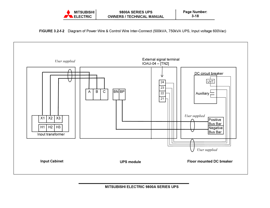
FIGURE 3.2-f-2 Diagram of Power Wire & Control Wire Inter-Connect (500kVA, 750kVA UPS, Input voltage 600Vac)
User supplied
| X1 | X2 | X3 |
|
|
|
|
|
|
H1 H2 H3
Input transformer
External signal terminal
|
|
|
| 24 | |
A | B | C | BN BP | 23 | |
22 | |||||
|
|
|
| ||
|
|
|
| 21 |
DC circuit breaker
UVT
Auxiliary 
User supplied
Positive
Bus Bar
Negative
Bus Bar
User supplied
Input Cabinet | UPS module | Floor mounted DC breaker |
