MITSUBISHI
![]() ELECTRIC
ELECTRIC
9800A SERIES UPS
OWNERS / TECHNICAL MANUAL
Page Number:
The Bypass Input circuit breaker (MCCB) for protection of the UPS and cables are field supplied and field installed. (See WARNING 2 on page
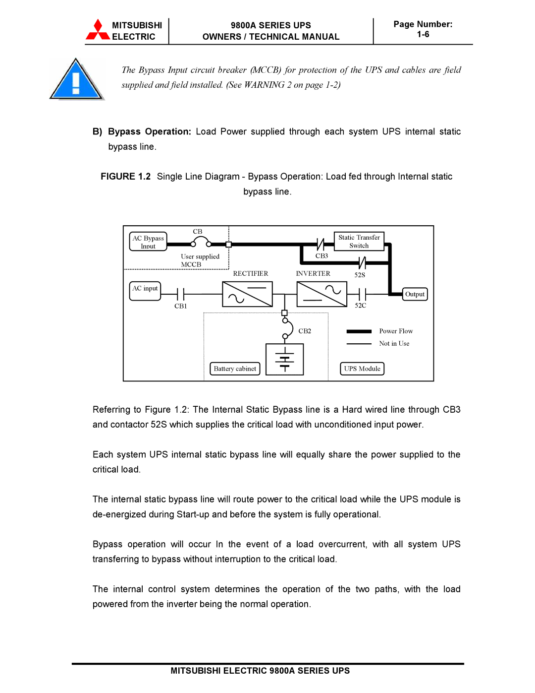
B)Bypass Operation: Load Power supplied through each system UPS internal static bypass line.
FIGURE 1.2 Single Line Diagram - Bypass Operation: Load fed through Internal static bypass line.
CB
AC Bypass
Input
User supplied
MCCB
RECTIFIER
AC input
CB1
Static Transfer
Switch
CB3
INVERTER 52S
52C
Output |
|
|
|
|
|
|
| CB2 |
| Power Flow | |
|
|
|
|
|
|
|
| |||
|
|
|
|
|
|
|
| |||
|
|
|
|
|
|
|
| |||
|
|
|
|
|
|
|
|
|
| Not in Use |
|
|
|
|
|
|
|
|
|
| |
|
|
|
|
|
|
|
|
|
| |
|
|
|
|
|
|
|
|
|
|
|
|
|
|
|
|
|
|
|
|
|
|
|
|
|
|
|
|
|
|
|
|
|
Battery cabinet
UPS Module
Referring to Figure 1.2: The Internal Static Bypass line is a Hard wired line through CB3 and contactor 52S which supplies the critical load with unconditioned input power.
Each system UPS internal static bypass line will equally share the power supplied to the critical load.
The internal static bypass line will route power to the critical load while the UPS module is
Bypass operation will occur In the event of a load overcurrent, with all system UPS transferring to bypass without interruption to the critical load.
The internal control system determines the operation of the two paths, with the load powered from the inverter being the normal operation.