MITSUBISHI | 9800A SERIES UPS | Page Number: |
ELECTRIC | OWNERS / TECHNICAL MANUAL |
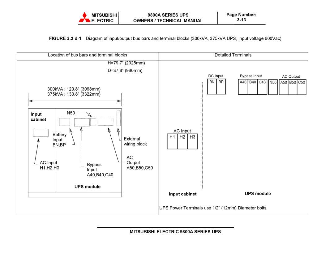
FIGURE 3.2-d-1 Diagram of input/output bus bars and terminal blocks (300kVA, 375kVA UPS, Input voltage 600Vac)
Location of bus bars and terminal blocks |
|
|
| Detailed Terminals |
|
| |||
|
| H=79.7” (2025mm) |
|
|
|
|
|
|
|
|
| D=37.8” (960mm) |
|
| DC Input | Bypass Input |
|
| |
|
|
|
|
|
| AC Output | |||
|
|
|
|
| BN | BP | A40 B40 C40 | N50 | A50 B50 C50 |
300kVA : 120.8” (3068mm) |
|
|
|
|
|
|
|
| |
375kVA : 130.8” (3322mm) |
|
|
|
|
|
|
|
| |
Input | N50 |
|
|
|
|
|
|
|
|
cabinet |
|
|
|
|
|
|
|
|
|
Battery |
|
| AC Input |
|
|
|
| ||
| External | H1 | H2 | H3 |
|
|
|
| |
Input |
|
|
|
|
| ||||
|
|
|
|
|
|
|
| ||
BN,BP |
| wiring block |
|
|
|
|
|
|
|
|
| AC |
|
|
|
|
|
|
|
AC Input | Bypass | Output |
|
|
|
|
|
|
|
H1,H2,H3 | A50,B50,C50 |
|
|
|
|
|
|
| |
Input |
|
|
|
|
|
|
| ||
|
|
|
|
|
|
|
|
| |
| A40,B40,C40 |
|
|
|
|
|
|
| |
| UPS module |
|
|
|
|
|
|
|
|
|
|
| Input cabinet |
| UPS module |
| |||
|
|
| UPS Power Terminals use 1/2” (12mm) Diameter bolts. |
|
| ||||