3-3 Electrical Connections
The standard Slide Gate/Auger blending system is designed to operate on 120/1/60 supply voltage (220/1/50 CE models are also available). The current requirements vary with the blender’s size and throughput rating. For exact current requirements, check the blender serial number tag, located on the rear plate of the mixer section.
If a step down transformer was provided, it should never be used to power anything other than the blender. Loading equipment, etc. must be powered by another power source. As well as possibly overloading the transformer, the additional equipment may induce power line noise that may affect the operation of the blending system.
The transformer will be mounted and wired by the customer or your installer. If company or local codes require fusing or disconnects, these items must be supplied, wired, and mounted by the customer.
Note: Each blending system MUST be connected to a separate source of power. Do not connect other electrical equipment, especially self- contained hopper loaders, on the same line as the blending system.
Ensure that the power entrance location on the blender panel remains unchanged. Make sure that the proper size wire and proper wire routing techniques are used when installing the supply wiring to the control panel. Care must be taken to ensure that the supply wiring does not interfere with the low voltage DC wiring.
The blender is equipped with a plug that functions as the disconnect device (See Figure 11 on Page 27 for an example). The mating receptacle must be installed no higher than 5’ feet
(1.6 m) above the floor. Make sure your installation conforms to your regional electrical standards.
3-4 Pneumatic Connections
The Slide Gate/Auger blending system uses
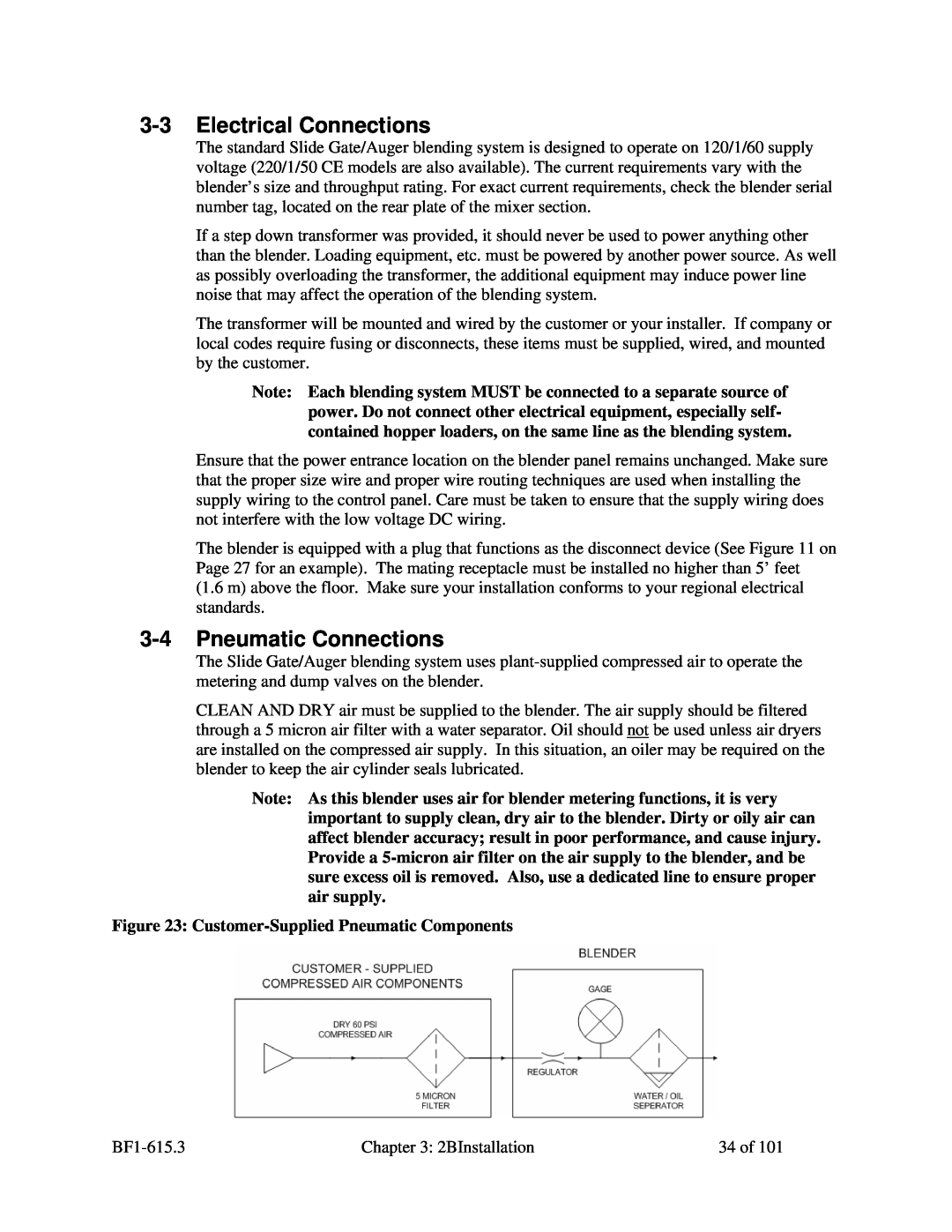
CLEAN AND DRY air must be supplied to the blender. The air supply should be filtered through a 5 micron air filter with a water separator. Oil should not be used unless air dryers are installed on the compressed air supply. In this situation, an oiler may be required on the blender to keep the air cylinder seals lubricated.
Note: As this blender uses air for blender metering functions, it is very important to supply clean, dry air to the blender. Dirty or oily air can affect blender accuracy; result in poor performance, and cause injury. Provide a
Figure 23: Customer-Supplied Pneumatic Components
Chapter 3: 2BInstallation | 34 of 101 |