The manufacturer provides all pneumatic lines on the blender piped to a single ¼” NPT standard pipe thread fitting. The Slide Gate/Auger blending system requires approximately 1 cfm (1.7 m³/hr) @ 60 psi (4.14 bar) maximum air pressure for proper operation.
The working pressure of the blender cylinders is not to exceed 60 psi (4.14 bar). This is adjustable by the regulator supplied on the rear panel of the blender. It is important to prevent fluctuation in the air pressure to the blender by not installing the unit on an airline. If this is the case, an accumulator tank with a check valve may have to be provided by the customer to ensure the blender a steady air supply.
Caution! To prevent damage to the equipment, do not exceed 60 psi (4.14 bar) air pressure.
Caution! Always disconnect the compressed air supply when working on any part of the blender.
3-5 Initial Set-up
This section will discuss the mechanical setup and control system setup of the Slide Gate blending system. After reading this section, you should be familiar with the mechanical setup and the electronic control setup of the blending system.
Mechanical Set-up
Stroke Limiters for Metering Gates
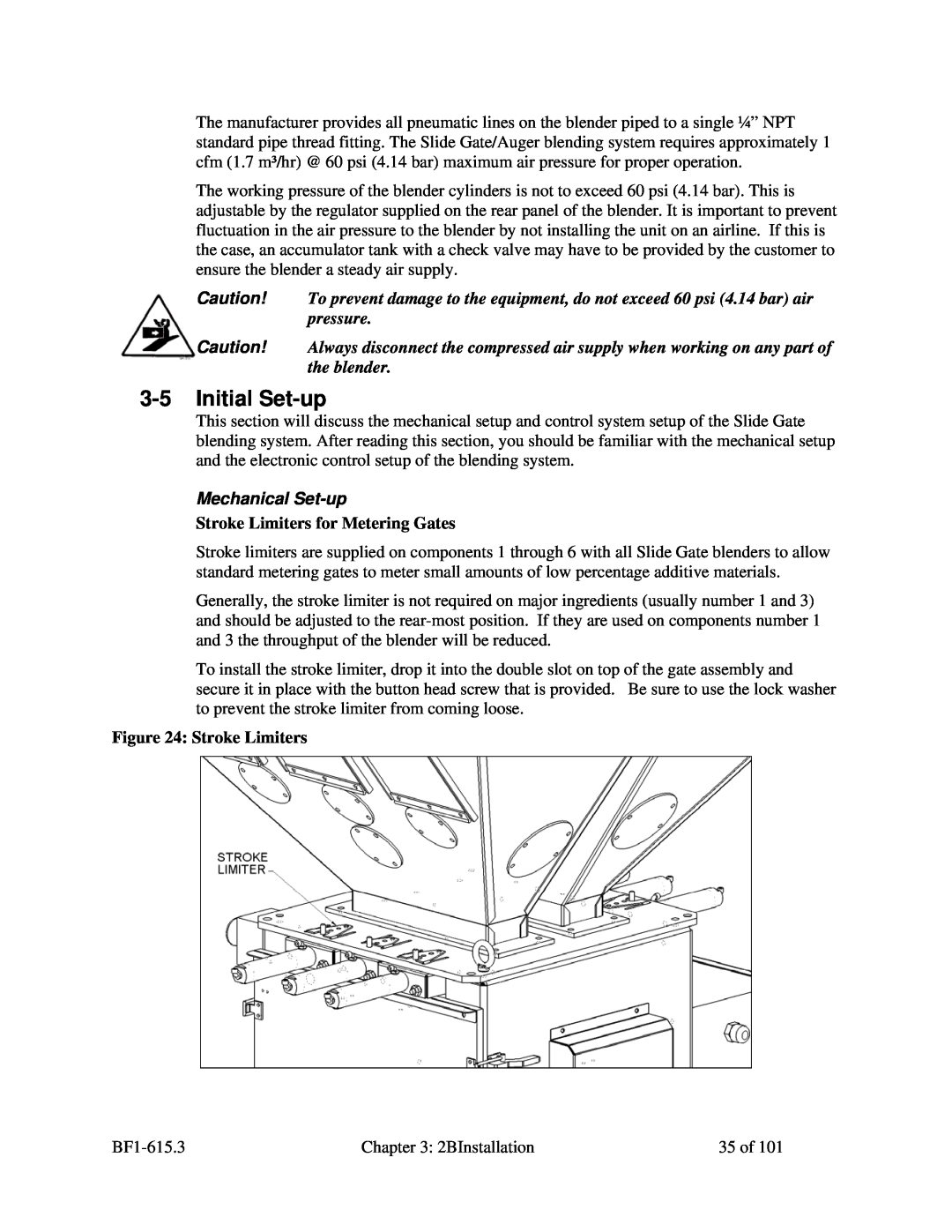
Stroke limiters are supplied on components 1 through 6 with all Slide Gate blenders to allow standard metering gates to meter small amounts of low percentage additive materials.
Generally, the stroke limiter is not required on major ingredients (usually number 1 and 3) and should be adjusted to the
To install the stroke limiter, drop it into the double slot on top of the gate assembly and secure it in place with the button head screw that is provided. Be sure to use the lock washer to prevent the stroke limiter from coming loose.
Figure 24: Stroke Limiters
Chapter 3: 2BInstallation | 35 of 101 |