Manuals
/
Mitsubishi Electronics
/
Kitchen Appliance
/
Blender
Mitsubishi Electronics
882.00273.00 Hopper Sub-assembly, Typical Hopper Assembly Parts List
Models:
882.00273.00
1
77
101
101
Download
101 pages
4.53 Kb
74
75
76
77
78
79
80
81
Troubleshooting
Specifications
Install
Drawings and Diagrams
Alarm Setup
Password
Calibration Error
Mix Timer
Warranty
Maintenance
Page 77
Image 77
Page 76
Page 78
Page 77
Image 77
Page 76
Page 78
Contents
Gravimetric Slide Gate Batch Blender Mitsubishi Controller
Write Down Your Serial Numbers Here For Future Reference
Part Number Bulletin Number BF1-615.3 Effective 11/07/07
We are committed to a continuing program of product improvement
Unpacking and Inspection
Shipping Info
In the Event of Shipping Damage
If the Shipment is Not Complete
Credit Returns
Warranty Returns
CHAPTER 1 SAFETY
Table of Contents
CHAPTER 3 INSTALLATION
CHAPTER 2 FUNCTIONAL DESCRIPTION
CHAPTER 6 TROUBLESHOOTING
CHAPTER 5 MAINTENANCE
CHAPTER 4 OPERATION
CHAPTER 7 APPENDIX
Hopper Additive Feeder Sub-Assembly Optional
Safety Symbols Used in this Manual
Chapter 1 Safety
1-1 How to Use This Manual
Description
Figure 1 Safety Tags and Warning Labels
CAUSING BODILY INJURY EXISTS ANY TIME THE POWER IS ON
1-2 Warnings and Precautions
Wear SAFETY GLASSES and WORK GLOVES
Use care when LOADING, UNLOADING, RIGGING, or MOVING this equipment
Operator Responsibility
1-3 Responsibility
General Responsibility
REMEMBER
Reporting a Safety Defect
Maintenance Responsibility
Customer Service
Accessories
Chapter 2 Functional Description
2-1 Models Covered in This Manual
Figure 3 Typical Blender Assembly
Figure 2 Equipment Specifications
Dimensions and Specifications
2500
Mechanical Features
2-3 Typical Features and Components
Controller Features
Figure 4 Typical Mitsubishi Controller Touch Screen Display
Supply Hoppers
Figure 5 Typical Hopper Assembly
System Component Description
Slide Gates
Weigh Hopper
Figure 6 Typical Slide Gate Assembly
Figure 7 Typical Weigh Hopper Assembly
Operator Control Panel Display
Figure 8 Typical Mixer Assembly
Mix Chamber
Figure 10 Controller Pushbuttons & Touchscreen Tags
Figure 9 Typical Mitsubishi Controller Touch Screen Display
Button
Function
22 of
Figure 11 Typical Operator Screens
23 of
Figure 12 Typical Setup Screens
24 of
2-4 Optional Components
Figure 13 Mixer Slide Gate Switch Positions
Pneumatic Slide Gate below Mixer
Position
Figure 16 Typical Additive Feeder Configuration
Figure 15 Typical R.A.M. Hopper Blender Configuration
Regrind Auger Metering R.A.M. Hopper
Additive Feeder Hopper
Safety Circuit Standards
2-5 Safety Features
Safety Device Lock-Outs
Fail Safe Operation
Figure 18 Twist Cap Plug
Figure 17 Electrical Disconnect Plug
Twist Cap Plug Connected to Each Feeder Auger Motor
Figure 19 Electrical Safety Interlock Switch Located on mixer door
Electric Safety Interlock Switch
3-2 Mechanical Installation
Chapter 3 Installation
3-1 Uncrating the Equipment
Figure 20 Blender Lifting Lugs 1 on each side
Machine Mount
Mounting Configurations
Site Requirements
Mezzanine Mount
Note Larger blenders need to be braced as part of the installation
Figure 21 Typical Mezzanine Mounted Batch Blender
GRAVIMETRIC BATCH BLENDER MEZZANINE SUPPLIED BY CUSTOMER
Figure 22 Typical Floor Mount Central Blender Layout
Floor Mount Central Blender
Figure 23 Customer-Supplied Pneumatic Components
3-3 Electrical Connections
3-4 Pneumatic Connections
Mechanical Set-up
3-5 Initial Set-up
Stroke Limiters for Metering Gates
Figure 24 Stroke Limiters
Figure 25 Weigh Hopper
Weigh Hopper Installation
Final Connections
Figure 26 Display Startup Screen
Controller Set-up
Figure 27 Display Main Recipe Screen
Blender Controller Menu Structure
Blender Calibration
Figure 29 Display Calibration Screen
Figure 28 Display Calibration Menu Screen
Enter in the Calibration Weight Press here to perform the calibration
Current Loadcell Bits Follow Instructions
Figure 30 Display Alarm Flags & Feeder Setup Screen
Alarm Setup
Feeder Calibration Auger Blenders
Select a Feeder to Configure Change the Alarm Silence Delay
Figure 31 Ethernet Setup Screen
Network Setup
Setting Date and Time
Figure 32 PanelView Configuration Screen
Additional Setup Parameters
3-6 Initial Startup
Chapter 4 Operation
Quick Start Procedure
4-1 Start-up
General Operation
Note Press “Push to Start or Stop” button to start blender
4-2 Operation Procedures
Existing Recipes
Figure 34 Typical Manual Control Operator Screen
Operator Displays
Figure 33 Typical Recipe Entry Operator Screen
Recipe Entry Formats
Figure 35 Typical Inventory Display Operator Screen
Recipe Format Menu
“Quickset” Mode Most common in injection molding
Page
Recipe Setup
Switching Modes
“Percentage” Mode Most common in extrusion and blow molding
Figure 37 Example Calculations of a 4-component blend in “Parts” mode
Blender
Figure 38 Typical Batch Sizes
Batch Size lbs
Inventory Shutdown
Mixer and Dump Setup
Auto Start Feature
Mix Timer
Figure 40 Typical Mixer and Dump Setup Operator Screen
Weigh Hopper Dump Delay Time
Re-Mix Timer
Weigh Hopper Dump Time
Figure 41 Typical “Out of Material” Alarm Screen
Alarm Flags
Weigh Hopper Dump Cycle
Mixer Dump Time
MAX HOPPER WEIGHT EXCEEDED check batch size
Figure 42 Typical “Maximum Hopper Weight” Alarm Screen
Figure 43 Typical “Calibration Error” Alarm Screen
Figure 44 Typical “Power Interruption” Alarm Screen
Figure 46 Typical “E-Stop Activated” Alarm Screen
Figure 45 Typical “PLC Battery Low” Alarm Screen
PLC BATTERY LOW
Figure 47 Typical Manual Control Operator Screen
Feeder Clean Out
Tree Diagram in section 3-5 of this manual
Recipe Book
Figure 48 Typical Recipe Book Operator Screen
Display Recipe Contents
Save Running Recipe to the Book
Load a Saved Recipe from the Book
Color Changes
Erase Recipe or Entire Book
Figure 49 Typical Inventory Shutdown Operator Screen
4-3 Shut-down
5-1 Preventative Maintenance Schedule
Chapter 5 Maintenance
Figure 50 Sample Preventative Maintenance Schedule
System model #
5-3 Corrective Maintenance
5-2 Preventative Maintenance
Electrical
Internal Components of the Control Panel
Note The alarm contact has a maximum load of 3 amps
Input Signals to Programmable Controller
Output Signals from Programmable Controller
Problem
Chapter 6 Troubleshooting
6-1 Introduction
Corrective action
Corrective action
Problem
Corrective action
warranty will be voided
Service Department
Equipment Specifications
7-1 Technical Specifications
Figure 52 Equipment Specifications
Chapter 7 Appendix
Annex B Information
Figure 53 Typical Final Assembly Parts List
7-2 Drawings and Diagrams
Final Assembly
75 of
Mixer Sub-Assembly
A0770319
Figure 54 Typical Mixer Assembly Parts List
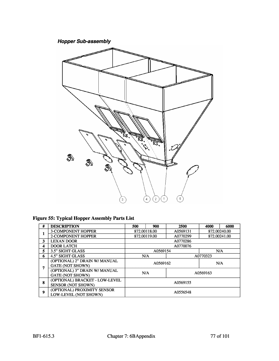
Figure 55 Typical Hopper Assembly Parts List
Hopper Sub-assembly
Figure 56 Typical R.A.M. Hopper Assembly Parts List
Hopper R.A.M. Regrind Auger Metering Sub-Assembly Optional
Figure 57 Typical Additive Feeder Hopper Assembly Parts List
Hopper Additive Feeder Sub-Assembly Optional
Figure 58 Typical Weigh Hopper Assembly Parts List
Weigh Hopper Sub-assembly
Figure 59 Typical Slidegate Assembly Parts List
Slide Gate Sub-assembly
Figure 60 Typical Knife Gate below mixer Assembly Parts List
Knife Gate Sub-assembly HD Optional
Figure 61 Typical Knife Gate floor stand Assembly Parts List
Knife Gate Sub-assembly RD Optional
Control Panel Layout
Figure 62 Typical Mitsubishi Controller Main Parts List
Figure 63 Typical Mitsubishi Display Main Parts List
Spare Parts Kits
Figure 64 Blender Spare Parts Listing
Passwords
7-4 Addendum Service Supervisor Information
Programmable Settings
Figure 65 Typical Operator Setup Screen
Factory Setup Menu
Figure 66 Typical Engineering Only Setup Screen
Advanced Weight Options Screen
Metering Test Screen
Feed Algorithm Options Screen
Figure 68 Typical Advanced Weight Options Screen
Figure 69 Typical Feed Algorithm Options Screen
Feed Calibration Options Screen
Figure 72 Typical Feeder Setup Screen
Feeder Setup
Mechanical Options Screen
Figure 71 Typical Mechanical Options Screen
Figure 74 Typical Ethernet Setup Screen
Customer Setup Menu
Units
Figure 73 Typical Units Screen
Figure 76 Typical Alarm Log Screen
Figure 75 Typical Alarm Flags & Feeder Setup Screen
Alarm Log
BF1-615.3
Factory Default Setup Parameters
Chapter 7 6BAppendix
92 of
VIRGIN
93 of
Note ITEMS MARKED R ARE READ ONLY AND ITEMS MARKED RW ARE READ/WRITE
7-5 Mitsubishi Communications Manual
GENERAL BLENDER INFO
BLENDER STARTING AND STOPPING
BLENDER ALARMS
INVENTORY INFO
CURRENT RECIPE INFO THIS IS THE RECIPE THAT IS CURRENTLY BEING MADE
RECIPE INFO THIS IS WHERE YOU RIGHT THE NEW RECIPE TO
RECIPE BOOK MANIPULATION
TARGETS VS. ACTUAL WEIGHT INFO
FIXED DECIMAL EXPLANATION
Alarm Number Explanation
UNTIL THE HOPPER FEEDS MATERIAL INTO THE NEW BATCH
WRITING RECIPE EXPLANATION
RECORDING THE TARGETS VS. ACTUALS FOR EACH BATCH
7-6 Technical Assistance
Service Department
Parts Department
Sales Department
Top
Page
Image
Contents