10.2. Refrigerant piping system
|
|
|
|
|
|
|
|
|
|
|
|
|
|
|
|
|
|
|
|
|
|
|
|
|
|
|
|
|
|
|
|
|
|
|
|
|
|
|
|
|
|
|
|
|
|
|
|
| Constant |
| Variable |
|
| ||||||||||||
|
|
|
|
|
|
|
|
|
|
|
|
|
|
|
|
|
|
|
|
|
|
|
|
|
|
|
|
|
|
|
|
|
|
|
|
|
|
|
|
|
|
|
|
|
|
|
| capacity unit | capacity unit |
|
| ||||||||||||||
|
|
|
|
| Constant | Variable |
|
|
|
|
|
|
|
|
|
|
|
|
|
|
|
|
|
|
|
|
|
|
|
|
|
|
|
|
|
|
|
|
|
|
|
|
|
|
|
| Distributer (gas) (optional) | ||||||||||||||||||
|
|
|
|
| capacity unit | capacity unit |
|
|
|
|
|
|
|
|
|
|
|
|
|
|
|
|
|
|
|
|
|
|
|
|
|
|
|
|
|
|
|
|
|
|
|
|
|
|
|
| |||||||||||||||||||
|
|
|
|
|
|
|
|
|
|
|
|
|
|
|
|
|
|
|
|
|
|
|
|
|
|
|
|
|
|
|
|
|
|
|
|
|
|
|
|
|
|
|
|
|
|
|
|
| |||||||||||||||||
|
|
|
|
|
|
|
|
|
|
|
|
|
|
|
|
|
|
|
|
|
|
|
|
|
|
|
|
|
|
| Oil balance pipe (optional) I |
|
|
|
|
|
|
|
|
|
|
|
|
|
| Gas line B |
|
| |||||||||||||||||
|
|
|
|
|
|
|
|
|
|
|
|
|
|
|
|
|
|
|
|
|
|
|
|
|
|
|
|
|
|
| (for distribution within the unit) |
|
|
|
|
|
|
|
|
|
|
|
|
|
|
|
| ||||||||||||||||||
|
|
|
|
|
|
|
|
|
|
|
|
|
|
|
|
|
|
|
|
|
|
|
|
|
|
|
|
|
|
|
|
|
|
|
|
|
|
|
|
| Gas line A |
|
|
|
|
|
|
|
|
|
|
|
|
|
| Liquid line B |
|
| |||||||
|
|
|
|
|
|
|
|
|
|
|
|
|
|
|
|
|
|
|
|
|
|
|
|
|
|
|
|
|
|
|
|
|
|
|
|
|
|
|
|
|
|
|
|
|
|
|
|
|
|
|
|
|
|
|
|
| |||||||||
|
|
|
|
|
|
|
|
|
|
|
|
|
|
|
|
|
|
|
|
|
|
|
|
|
|
|
|
|
|
|
|
|
|
|
|
|
|
|
|
|
|
|
|
|
|
|
|
|
|
|
|
|
|
|
|
| |||||||||
|
|
|
|
|
|
|
|
|
|
|
|
|
|
|
|
|
|
|
|
|
|
|
|
|
|
|
|
|
|
|
|
|
|
|
|
|
|
|
|
|
|
|
|
|
|
|
|
|
|
|
|
|
|
|
|
| |||||||||
|
|
|
|
|
|
|
|
|
|
|
|
|
|
|
|
|
|
|
|
|
|
|
|
|
|
|
|
|
|
|
|
|
|
|
|
|
|
|
|
| Liquid line A |
|
|
|
|
|
|
|
|
|
|
|
|
|
|
|
| ||||||||
|
|
|
|
|
|
| A | G | B |
| Note 1 |
|
|
|
|
|
|
|
|
|
|
|
|
|
|
|
|
|
|
|
|
|
|
|
|
|
|
|
|
|
|
|
|
| Distributer (liguid) (optional) | ||||||||||||||||||||
|
|
|
|
|
|
|
|
|
|
|
|
|
|
|
|
|
|
|
|
|
|
|
|
|
|
|
|
|
|
|
|
|
|
|
|
|
|
|
|
|
|
|
|
|
|
|
| ||||||||||||||||||
|
|
|
|
|
|
|
|
|
|
| Distributer |
|
|
|
|
|
|
|
|
|
|
|
| L |
|
|
|
|
|
|
|
|
|
| Gas line (main) C |
|
|
|
|
|
|
|
| Liquid line (main) C | |||||||||||||||||||||
|
|
|
|
|
|
|
|
|
|
|
|
|
|
|
|
|
|
|
|
|
|
|
|
|
|
|
|
|
|
|
|
|
|
|
|
|
|
|
| ||||||||||||||||||||||||||
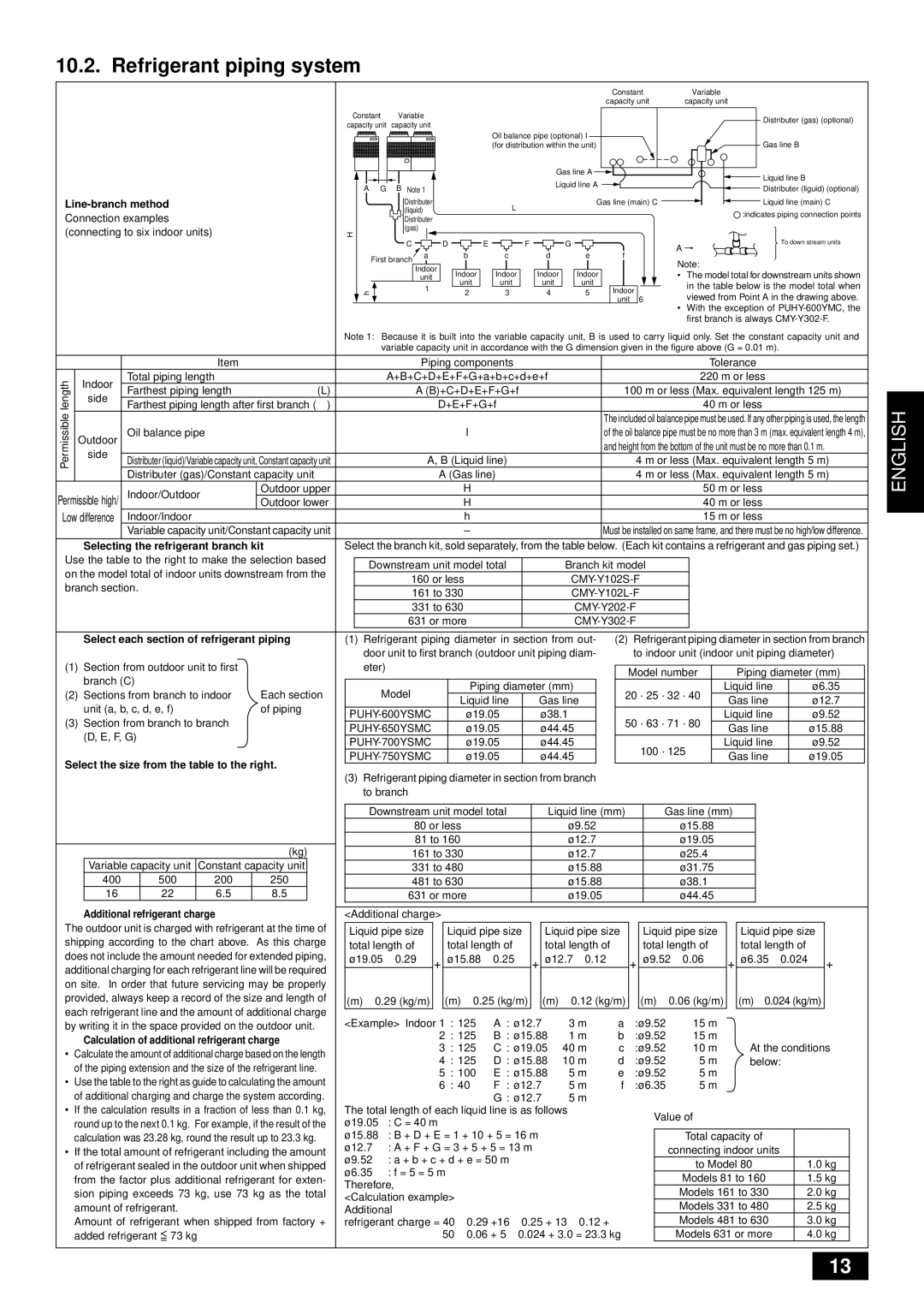
Connection examples |
|
|
|
|
|
|
|
|
|
| (liquid) |
|
|
|
|
|
|
|
|
|
|
|
|
|
|
|
|
|
|
|
|
|
|
|
|
|
|
|
|
|
|
|
|
|
|
| :indicates piping connection points | ||||||||||||||||||
|
|
|
|
|
|
|
|
|
| Distributer |
|
|
|
|
|
|
|
|
|
|
|
|
|
|
|
|
|
|
|
|
|
|
|
|
|
|
|
|
|
|
|
|
|
|
|
|
|
| |||||||||||||||||
|
|
|
|
|
|
|
|
|
|
|
|
|
|
|
|
|
|
|
|
|
|
|
|
|
|
|
|
|
|
|
|
|
|
|
|
|
|
|
|
|
|
|
|
|
|
|
|
|
|
|
|
|
| ||||||||||||
(connecting to six indoor units) |
| H |
|
| (gas) |
|
|
|
|
|
|
|
|
|
|
|
|
|
|
| R |
|
|
|
|
|
|
|
|
|
|
|
|
|
|
|
|
|
|
|
|
|
|
|
|
| To down stream units | ||||||||||||||||||
|
|
|
|
|
|
|
|
|
|
|
|
|
|
|
|
|
|
|
|
|
|
|
|
|
|
|
|
|
|
|
|
|
|
|
|
|
|
|
|
| |||||||||||||||||||||||||
|
|
|
|
|
|
|
|
|
|
|
|
|
|
| C |
|
|
|
|
|
|
| D |
|
|
|
|
|
| E |
|
|
|
|
| F |
|
|
|
|
| G |
|
|
|
|
|
|
|
|
|
|
| A |
|
|
|
|
|
|
| ||||
|
|
|
|
|
|
|
|
| First branch |
| a |
|
|
|
|
|
| b |
|
|
|
| c |
|
|
|
|
| d |
|
|
| e |
|
|
|
| f |
|
|
| Note: |
|
|
|
|
|
|
|
|
| ||||||||||||||
|
|
|
|
|
|
|
|
|
|
|
|
|
|
|
|
|
|
|
|
|
|
|
|
|
|
|
|
|
|
|
|
|
|
|
|
|
|
|
|
|
|
|
|
|
|
|
|
|
|
|
|
|
|
|
|
|
|
|
|
|
|
| |||
|
|
|
|
|
|
|
|
|
|
|
|
|
|
|
| Indoor |
|
|
|
|
|
|
|
|
|
|
|
|
|
|
|
|
|
|
|
|
|
|
|
|
|
|
|
|
|
|
|
|
|
|
|
|
|
|
|
|
| ||||||||
|
|
|
|
|
|
|
|
|
|
|
|
|
|
|
| unit |
|
|
| Indoor |
| Indoor |
| Indoor |
| Indoor |
|
|
|
|
|
| • | The model total for downstream units shown | |||||||||||||||||||||||||||||||
|
|
|
|
|
|
|
|
|
|
|
|
|
|
|
| 1 |
|
|
|
|
|
| unit |
| unit |
| unit |
| unit |
|
|
|
|
|
|
| in the table below is the model total when | ||||||||||||||||||||||||||||
|
|
|
|
|
|
| h |
|
|
|
|
|
|
|
|
|
| 2 |
|
|
| 3 |
|
|
|
| 4 |
|
| 5 |
|
|
|
| Indoor |
|
| viewed from Point A in the drawing above. | |||||||||||||||||||||||||||
|
|
|
|
|
|
|
|
|
|
|
|
|
|
|
|
|
|
|
|
|
|
|
|
|
|
|
|
|
|
|
|
|
|
|
|
|
|
|
|
|
|
|
|
|
|
|
|
| unit | 6 |
| ||||||||||||||
|
|
|
|
|
|
|
|
|
|
|
|
|
|
|
|
|
|
|
|
|
|
|
|
|
|
|
|
|
|
|
|
|
|
|
|
|
|
|
|
|
|
|
|
|
|
|
|
| |||||||||||||||||
|
|
|
|
|
|
|
|
|
|
|
|
|
|
|
|
|
|
|
|
|
|
|
|
|
|
|
|
|
|
|
|
|
|
|
|
|
|
|
|
|
|
|
|
|
|
|
|
|
|
|
|
|
| • | With the exception of | ||||||||||
|
|
|
|
|
|
|
|
|
|
|
|
|
|
|
|
|
|
|
|
|
|
|
|
|
|
|
|
|
|
|
|
|
|
|
|
|
|
|
|
|
|
|
|
|
|
|
|
|
|
|
|
|
|
| first branch is always | ||||||||||
|
|
|
|
| Note 1: Because it is built into the variable capacity unit, B is used to carry liquid only. Set the constant capacity unit and | ||||||||||||||||||||||||||||||||||||||||||||||||||||||||||||
|
|
|
|
|
|
|
|
|
|
| variable capacity unit in accordance with the G dimension given in the figure above (G = 0.01 m). |
|
| ||||||||||||||||||||||||||||||||||||||||||||||||||||
|
|
|
|
|
|
|
|
|
|
|
|
|
|
|
|
|
|
|
|
|
|
|
|
|
|
|
|
|
|
|
|
|
|
|
|
|
|
|
|
|
|
|
|
|
|
|
|
|
|
|
|
|
|
|
|
|
|
|
|
|
|
|
|
| |
|
|
| Item |
|
|
|
|
|
|
|
|
|
|
|
|
| Piping components |
|
|
|
|
|
|
|
|
|
|
|
|
|
|
|
|
|
|
|
| Tolerance |
|
| |||||||||||||||||||||||||
length |
| Indoor | Total piping length |
|
|
|
|
|
|
|
| A+B+C+D+E+F+G+a+b+c+d+e+f |
|
|
|
|
|
|
|
|
|
|
|
|
|
| 220 m or less |
|
| ||||||||||||||||||||||||||||||||||||
| Farthest piping length after first branch (r) |
|
|
|
|
|
|
|
|
|
|
|
|
|
|
|
|
| D+E+F+G+f |
|
|
|
|
|
|
|
|
|
|
|
|
|
|
|
|
|
|
|
| 40 m or less |
|
| |||||||||||||||||||||||
|
| side | Farthest piping length | (L) |
|
|
|
|
|
|
|
|
|
|
| A (B)+C+D+E+F+G+f |
|
|
|
|
|
|
|
|
|
|
|
|
| 100 m or less (Max. equivalent length 125 m) | |||||||||||||||||||||||||||||||||||
Permissible |
|
|
|
|
|
|
|
|
|
|
|
|
|
|
|
|
|
|
|
|
|
|
|
|
|
|
|
|
|
|
|
|
|
|
|
|
|
|
|
|
|
|
|
|
|
|
|
|
|
|
|
|
|
|
|
|
|
|
|
|
|
|
|
|
|
|
|
|
|
|
|
|
|
|
|
|
|
|
|
|
|
|
|
|
|
|
|
|
|
|
|
|
|
|
|
|
|
|
|
|
|
|
|
|
|
|
|
|
|
|
|
| The included oil balance pipe must be used. If any other piping is used, the length | ||||||||||||||||||
|
|
|
|
|
|
|
|
|
|
|
|
|
|
|
|
|
|
|
|
|
|
|
|
|
|
|
|
|
|
|
|
|
|
|
|
|
|
|
|
|
|
|
|
|
|
|
| ||||||||||||||||||
| Outdoor | Oil balance pipe |
|
|
|
|
|
|
|
|
|
|
|
|
|
|
|
|
|
|
|
|
|
|
| I |
|
|
|
|
|
|
|
|
|
|
|
|
|
|
|
|
| of the oil balance pipe must be no more than 3 m (max. equivalent length 4 m), | |||||||||||||||||||||
|
| side |
|
|
|
|
|
|
|
|
|
|
|
|
|
|
|
|
|
|
|
|
|
|
|
|
|
|
|
|
|
|
|
|
|
|
|
|
|
|
|
|
|
|
|
|
| and height from the bottom of the unit must be no more than 0.1 m. | |||||||||||||||||
|
| Distributer (liquid)/Variable capacity unit, Constant capacity unit |
|
|
|
|
|
|
|
|
|
|
|
|
|
| A, B (Liquid line) |
|
|
|
|
|
|
|
|
|
|
|
|
|
| 4 m or less (Max. equivalent length 5 m) | |||||||||||||||||||||||||||||||||
|
|
|
|
|
|
|
|
|
|
|
|
|
|
|
|
|
|
|
|
|
|
|
|
|
|
|
|
|
|
| |||||||||||||||||||||||||||||||||||
|
|
| Distributer (gas)/Constant capacity unit |
|
|
|
|
|
|
|
|
|
|
|
|
|
|
|
|
| A (Gas line) |
|
|
|
|
|
|
|
|
|
|
|
|
|
| 4 m or less (Max. equivalent length 5 m) | |||||||||||||||||||||||||||||
Permissible high/ | Indoor/Outdoor | Outdoor upper |
|
|
|
|
|
|
|
|
|
|
|
|
|
|
|
|
|
|
|
|
| H |
|
|
|
|
|
|
|
|
|
|
|
|
|
|
|
|
|
|
|
|
|
|
|
|
|
| 50 m or less |
|
| ||||||||||||
Outdoor lower |
|
|
|
|
|
|
|
|
|
|
|
|
|
|
|
|
|
|
|
|
| H |
|
|
|
|
|
|
|
|
|
|
|
|
|
|
|
|
|
|
|
|
|
|
|
|
|
| 40 m or less |
|
| ||||||||||||||
Low difference | Indoor/Indoor |
|
|
|
|
|
|
|
|
|
|
|
|
|
|
|
|
|
|
|
|
|
| h |
|
|
|
|
|
|
|
|
|
|
|
|
|
|
|
|
|
|
|
|
|
|
|
|
|
| 15 m or less |
|
| ||||||||||||
|
|
| Variable capacity unit/Constant capacity unit |
|
|
|
|
|
|
|
|
|
|
|
|
|
|
|
|
|
|
|
|
| – |
|
|
|
|
|
|
|
|
|
|
|
|
|
|
|
|
| Must be installed on same frame, and there must be no high/low difference. | ||||||||||||||||||||||
■ Selecting the refrigerant branch kit | Select the branch kit, sold separately, from the table below. (Each kit contains a refrigerant and gas piping set.) | ||||||||||||||||||||||||||||||||||||||||||||||||||||||||||||||||
Use the table to the right to make the selection based |
|
|
|
|
|
|
|
|
|
|
|
|
|
|
|
|
|
|
|
|
|
|
|
|
|
|
|
|
|
|
|
|
|
|
|
|
|
|
|
|
|
|
|
|
|
|
|
|
|
|
|
|
|
|
|
|
|
|
|
|
| ||||
|
|
| Downstream unit model total |
|
|
|
|
|
| Branch kit model |
|
|
|
|
|
|
|
|
|
|
| ||||||||||||||||||||||||||||||||||||||||||||
on the model total of indoor units downstream from the |
|
|
|
|
|
|
|
|
|
|
|
|
|
|
|
|
|
|
|
| |||||||||||||||||||||||||||||||||||||||||||||
|
|
|
|
|
|
|
|
|
|
| 160 or less |
|
|
|
|
|
|
|
|
|
|
|
|
|
|
|
|
|
|
|
|
|
| ||||||||||||||||||||||||||||||||
branch section. |
|
|
|
|
|
|
|
|
|
|
|
|
|
|
|
|
|
|
|
|
|
|
|
|
|
|
|
|
|
|
|
|
|
| |||||||||||||||||||||||||||||||
|
|
|
|
|
|
|
|
|
|
|
| 161 to 330 |
|
|
|
|
|
|
|
|
|
|
|
|
|
|
|
|
|
|
|
|
|
| |||||||||||||||||||||||||||||||
|
|
|
|
|
|
|
|
|
|
|
|
|
|
|
|
|
|
|
|
|
|
|
|
|
|
|
|
|
|
|
|
|
|
|
|
|
| ||||||||||||||||||||||||||||
|
|
|
|
|
|
|
|
|
|
|
|
|
|
|
| 331 to 630 |
|
|
|
|
|
|
|
|
|
|
|
|
|
|
|
|
|
|
|
|
|
|
| ||||||||||||||||||||||||||
|
|
|
|
|
|
|
|
|
|
|
|
|
|
| 631 or more |
|
|
|
|
|
|
|
|
|
|
|
|
|
|
|
|
|
|
|
|
|
|
| |||||||||||||||||||||||||||
|
|
|
|
|
|
|
|
|
|
|
|
|
|
|
|
|
|
|
|
|
|
|
|
|
|
|
|
|
|
|
|
|
|
|
|
|
|
|
|
|
|
|
|
|
|
|
|
|
|
|
|
|
|
|
|
|
|
|
|
|
|
| |||
■ |
| Select each section of refrigerant piping | (1) Refrigerant piping diameter in section from out- |
| (2) Refrigerant piping diameter in section from branch | ||||||||||||||||||||||||||||||||||||||||||||||||||||||||||||
|
|
|
|
|
|
| door unit to first branch (outdoor unit piping diam- |
|
|
| to indoor unit (indoor unit piping diameter) | ||||||||||||||||||||||||||||||||||||||||||||||||||||||
(1) | Section from outdoor unit to first |
|
|
| eter) |
|
|
|
|
|
|
|
|
|
|
|
|
|
|
|
|
|
|
|
|
|
|
|
|
|
|
|
|
|
|
|
|
|
|
|
|
|
|
|
|
|
|
|
|
|
|
|
|
|
|
|
|
|
| ||||||
|
|
|
|
|
|
|
|
|
|
|
|
|
|
|
|
|
|
|
|
|
|
|
|
|
|
|
|
|
|
|
|
|
|
|
|
|
|
|
|
| Model number |
|
|
| Piping diameter (mm) |
| |||||||||||||||||||
|
| branch (C) |
|
|
|
|
|
|
|
|
|
|
|
|
|
|
|
|
|
|
|
|
|
|
|
|
|
|
|
|
|
|
|
|
|
|
|
|
|
|
|
|
|
|
|
|
|
|
|
|
|
|
| ||||||||||||
|
| Each section |
|
|
|
|
|
| Model |
|
|
|
|
|
|
|
|
|
|
|
| Piping diameter (mm) |
|
|
|
|
|
|
|
|
|
|
|
|
|
|
|
|
| Liquid line |
| ø 6.35 |
| ||||||||||||||||||||||
(2) Sections from branch to indoor |
|
|
|
|
|
|
|
|
|
|
|
|
|
|
|
|
|
|
|
|
|
|
|
| 20 ·25 ·32 ·40 |
|
|
|
|
| |||||||||||||||||||||||||||||||||||
|
|
|
|
|
|
|
|
|
|
|
|
|
|
| Liquid line |
| Gas line |
|
|
|
|
| Gas line |
| ø 12.7 |
| |||||||||||||||||||||||||||||||||||||||
|
| unit (a, b, c, d, e, f) | of piping |
|
|
|
|
|
|
|
|
|
|
|
|
|
|
|
|
|
|
|
|
|
|
|
|
|
|
|
|
|
|
|
|
|
|
|
| ||||||||||||||||||||||||||
|
|
|
| ø 19.05 |
|
|
|
|
| ø 38.1 |
|
|
|
|
|
|
|
|
|
|
|
|
|
|
|
|
| Liquid line |
| ø 9.52 |
| ||||||||||||||||||||||||||||||||||
(3) Section from branch to branch |
|
|
|
|
|
|
|
|
|
|
|
|
|
| 50 ·63 ·71 ·80 |
|
|
|
|
| |||||||||||||||||||||||||||||||||||||||||||||
|
|
| ø 19.05 |
|
|
|
|
| ø 44.45 |
|
|
|
|
|
|
|
|
| Gas line |
| ø 15.88 |
| |||||||||||||||||||||||||||||||||||||||||||
|
| (D, E, F, G) |
|
|
|
|
|
|
|
|
|
|
|
|
|
|
|
|
|
|
|
|
|
|
|
|
|
|
| ||||||||||||||||||||||||||||||||||||
|
|
|
|
| ø 19.05 |
|
|
|
|
| ø 44.45 |
|
|
|
|
|
| 100 ·125 |
|
|
|
| Liquid line |
| ø 9.52 |
| |||||||||||||||||||||||||||||||||||||||
|
|
|
|
|
|
|
|
|
|
|
|
|
|
|
|
|
|
|
|
|
|
|
| ||||||||||||||||||||||||||||||||||||||||||
Select the size from the table to the right. |
|
| ø 19.05 |
|
|
|
|
| ø 44.45 |
|
|
|
|
|
|
|
|
|
| Gas line |
| ø 19.05 |
| ||||||||||||||||||||||||||||||||||||||||||
|
|
|
|
|
|
|
|
|
|
|
|
|
|
|
|
|
|
|
|
|
|
|
|
|
| ||||||||||||||||||||||||||||||||||||||||
|
|
|
|
|
|
|
|
|
|
|
|
|
|
|
|
|
|
|
|
|
|
|
|
|
|
|
|
|
|
|
|
|
|
|
|
|
|
|
|
|
|
|
|
|
|
|
|
|
|
|
|
|
|
|
|
|
|
|
|
| |||||
(3)Refrigerant piping diameter in section from branch to branch
|
|
|
|
|
|
|
|
| Downstream unit model total |
|
|
| Liquid line (mm) |
|
|
| Gas line (mm) |
|
|
|
|
| ||||||||
|
|
|
|
|
|
|
|
| 80 or less |
|
|
|
|
| ø 9.52 |
|
|
|
|
| ø 15.88 |
|
|
|
|
|
|
| ||
|
|
|
|
|
|
|
|
| 81 to 160 |
|
|
|
|
| ø 12.7 |
|
|
|
|
| ø 19.05 |
|
|
|
|
|
|
| ||
|
|
|
|
| (kg) |
|
|
|
|
|
|
|
|
|
|
|
|
|
|
|
|
|
|
|
|
|
| |||
|
|
|
|
| 161 to 330 |
|
|
|
|
| ø 12.7 |
|
|
|
|
| ø 25.4 |
|
|
|
|
|
|
| ||||||
|
| Variable capacity unit | Constant capacity unit |
|
|
|
|
|
|
|
|
|
|
|
|
|
|
|
|
|
|
|
|
|
|
|
| |||
| 331 to 480 |
|
|
|
|
| ø 15.88 |
|
|
|
|
| ø 31.75 |
|
|
|
|
|
|
| ||||||||||
|
| 400 | 500 | 200 | 250 |
|
|
|
|
|
|
|
|
|
|
|
|
|
|
|
|
|
|
|
|
|
|
|
|
|
|
|
| 481 to 630 |
|
|
|
|
| ø 15.88 |
|
|
|
|
| ø 38.1 |
|
|
|
|
|
|
| ||||||||
|
| 16 | 22 | 6.5 | 8.5 |
|
|
|
|
|
|
|
|
|
|
|
|
|
|
|
|
|
|
|
|
|
|
|
|
|
|
|
| 631 or more |
|
|
|
| ø 19.05 |
|
|
|
|
| ø 44.45 |
|
|
|
|
|
|
| |||||||||
|
| Additional refrigerant charge |
|
|
|
|
|
|
|
|
|
|
|
|
|
|
|
|
|
|
|
|
|
|
|
|
|
| ||
|
|
|
|
|
|
|
|
|
|
|
|
|
|
|
|
|
|
|
|
|
|
|
|
|
|
|
| |||
■ |
|
|
|
|
| <Additional charge> |
|
|
|
|
|
|
|
|
|
|
|
|
|
|
|
|
|
|
| |||||
The outdoor unit is charged with refrigerant at the time of |
|
|
|
|
|
|
|
|
|
|
|
|
|
| ||||||||||||||||
Liquid pipe size |
| Liquid pipe size |
| Liquid pipe size |
|
| Liquid pipe size |
| Liquid pipe size |
|
| |||||||||||||||||||
shipping according to the chart above. | As this charge | total length of |
| total length of |
|
| total length of |
|
|
| total length of |
| total length of |
|
| |||||||||||||||
does not include the amount needed for extended piping, | ø 19.05 ⋅ 0.29 | + | ø 15.88 ⋅ | 0.25 |
| + | ø 12.7 ⋅ 0.12 |
| + | ø 9.52 ⋅ 0.06 | + | ø 6.35 ⋅ | 0.024 | + α | ||||||||||||||||
additional charging for each refrigerant line will be required |
|
| ||||||||||||||||||||||||||||
|
|
|
|
|
|
|
|
|
|
|
|
|
|
|
|
|
|
|
|
|
| |||||||||
on site. In order that future servicing may be properly |
|
|
|
|
|
|
|
|
|
|
|
|
|
|
|
|
|
|
|
|
|
| ||||||||
provided, always keep a record of the size and length of | (m) ⋅ 0.29 (kg/m) |
| (m) ⋅ 0.25 (kg/m) |
| (m) ⋅ 0.12 (kg/m) |
| (m) ⋅ | 0.06 (kg/m) |
| (m) ⋅ 0.024 (kg/m) |
|
| ||||||||||||||||||
each refrigerant line and the amount of additional charge |
|
|
|
|
|
|
|
|
|
|
|
|
|
|
|
|
|
|
|
|
|
| ||||||||
<Example> Indoor 1 : 125 | A : ø 12.7 | 3 m | a | :ø 9.52 | 15 m |
|
|
|
|
|
|
| ||||||||||||||||||
by writing it in the space provided on the outdoor unit. |
|
|
|
|
|
|
| |||||||||||||||||||||||
■ Calculation of additional refrigerant charge |
| 2 : 125 | B : ø 15.88 | 1 m | b | :ø 9.52 | 15 m |
| At the conditions | |||||||||||||||||||||
| 3 : 125 | C : ø 19.05 | 40 m | c | :ø 9.52 | 10 m |
| |||||||||||||||||||||||
• Calculate the amount of additional charge based on the length |
|
| ||||||||||||||||||||||||||||
| 4 : 125 | D : ø 15.88 | 10 m | d | :ø 9.52 | 5 m |
| below: |
|
| ||||||||||||||||||||
| of the piping extension and the size of the refrigerant line. |
|
|
|
| |||||||||||||||||||||||||
|
| 5 : 100 | E : ø 15.88 | 5 m | e | :ø 9.52 | 5 m |
|
|
|
|
|
|
| ||||||||||||||||
• Use the table to the right as guide to calculating the amount |
|
|
|
|
|
|
|
| ||||||||||||||||||||||
| 6 : 40 | F : ø 12.7 | 5 m | f | :ø 6.35 | 5 m |
|
|
|
|
|
|
| |||||||||||||||||
| of additional charging and charge the system according. |
|
|
|
|
|
|
|
| |||||||||||||||||||||
|
|
|
|
| G : ø 12.7 | 5 m |
|
|
|
|
|
|
|
|
|
|
|
|
| |||||||||||
• | If the calculation results in a fraction of less than 0.1 kg, | The total length of each liquid line is as follows |
|
|
| Value of α |
|
|
|
|
|
|
| |||||||||||||||||
| round up to the next 0.1 kg. For example, if the result of the | ø 19.05 : C = 40 m |
|
|
|
|
|
|
|
|
|
|
|
|
|
|
|
| ||||||||||||
|
|
|
|
|
|
|
|
|
|
|
|
|
|
|
|
|
|
|
| |||||||||||
| calculation was 23.28 kg, round the result up to 23.3 kg. | ø 15.88 : B + D + E = 1 + 10 + 5 = 16 m |
|
|
|
|
|
| Total capacity of |
| α |
|
| |||||||||||||||||
• | If the total amount of refrigerant including the amount | ø 12.7 : A + F + G = 3 + 5 + 5 = 13 m |
|
|
|
|
|
| connecting indoor units |
|
|
|
| |||||||||||||||||
| of refrigerant sealed in the outdoor unit when shipped | ø 9.52 : a + b + c + d + e = 50 m |
|
|
|
|
|
|
|
|
| to Model 80 |
| 1.0 kg |
| |||||||||||||||
| ø 6.35 : f = 5 = 5 m |
|
|
|
|
|
|
|
|
|
|
|
|
| ||||||||||||||||
| from the factor plus additional refrigerant for exten- |
|
|
|
|
|
|
|
|
|
|
| Models 81 to 160 |
| 1.5 kg |
| ||||||||||||||
| Therefore, |
|
|
|
|
|
|
|
|
|
|
|
|
|
|
| ||||||||||||||
| sion piping exceeds 73 kg, use 73 kg as the total |
|
|
|
|
|
|
|
|
|
|
|
|
| Models 161 to 330 |
| 2.0 kg |
| ||||||||||||
| <Calculation example> |
|
|
|
|
|
|
|
|
|
|
|
|
| ||||||||||||||||
| amount of refrigerant. |
|
|
|
|
|
|
|
|
|
|
|
|
|
|
|
| Models 331 to 480 |
| 2.5 kg |
| |||||||||
|
|
|
|
|
| Additional |
|
|
|
|
|
|
|
|
|
|
|
|
|
|
| |||||||||
| Amount of refrigerant when shipped from factory + | refrigerant charge = 40 ⋅ | 0.29 +16 ⋅ | 0.25 + 13 ⋅ 0.12 + |
|
|
|
|
| Models 481 to 630 |
| 3.0 kg |
| |||||||||||||||||
| added refrigerant = 73 kg |
|
|
|
|
|
| 50 ⋅ | 0.06 + 5 ⋅ | 0.024 + 3.0 = 23.3 kg |
|
|
|
| Models 631 or more |
| 4.0 kg |
| ||||||||||||
|
|
|
|
|
|
|
|
|
|
|
|
|
|
|
|
|
|
|
|
|
|
|
|
|
|
|
| |||
ENGLISH
13