ENGLISH
<For constant capacity unit>
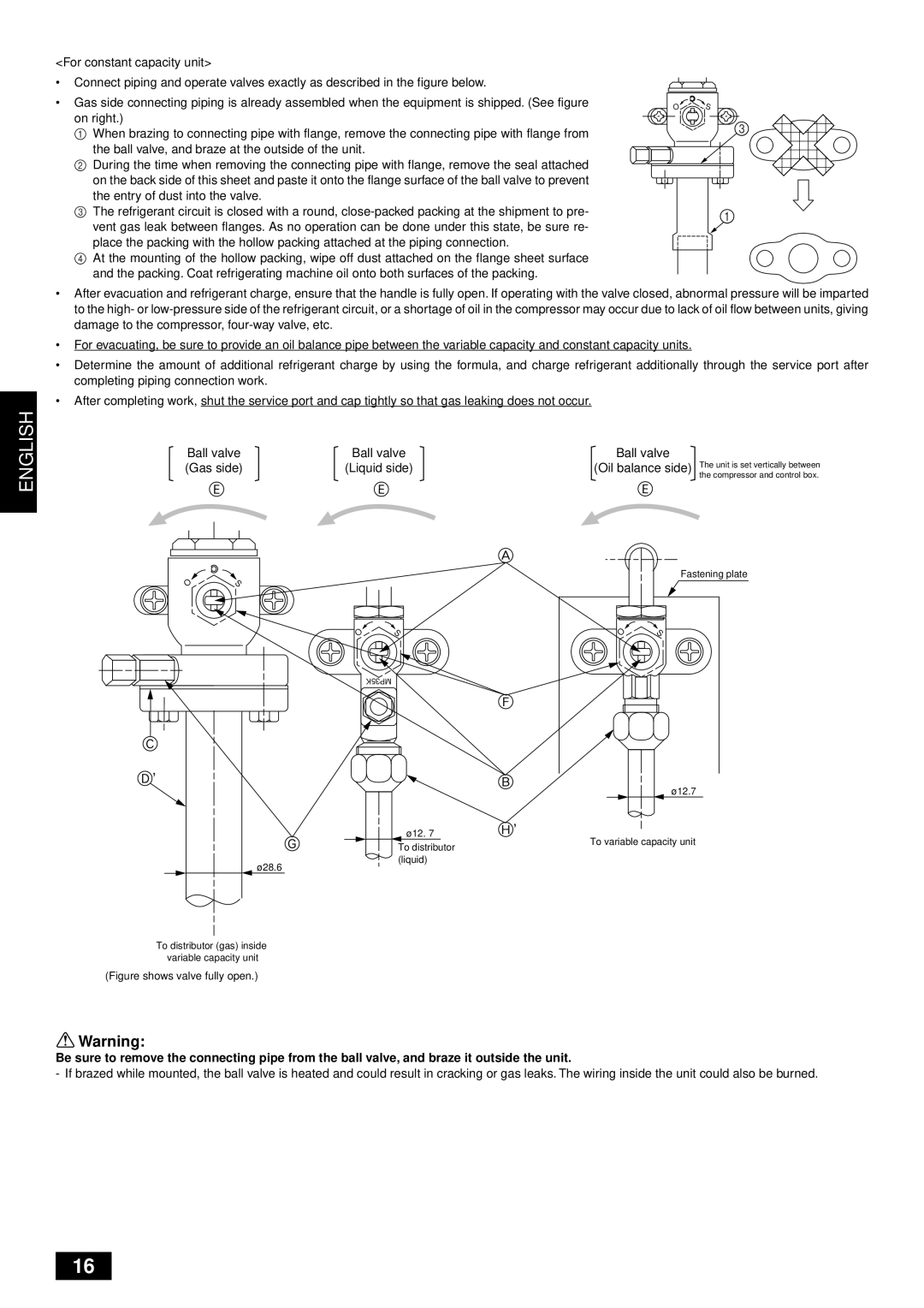
•Connect piping and operate valves exactly as described in the figure below.
Replace the solid packing.
• Gas side connecting piping is already assembled when the equipment is shipped. (See figure | O | S |
on right.) |
| 3 |
1 When brazing to connecting pipe with flange, remove the connecting pipe with flange from |
| |
|
| |
the ball valve, and braze at the outside of the unit. |
|
|
2During the time when removing the connecting pipe with flange, remove the seal attached on the back side of this sheet and paste it onto the flange surface of the ball valve to prevent the entry of dust into the valve.
3 The refrigerant circuit is closed with a round, | 1 | Hollow packing | |
vent gas leak between flanges. As no operation can be done under this state, be sure re- | |||
|
place the packing with the hollow packing attached at the piping connection.
4At the mounting of the hollow packing, wipe off dust attached on the flange sheet surface and the packing. Coat refrigerating machine oil onto both surfaces of the packing.
•After evacuation and refrigerant charge, ensure that the handle is fully open. If operating with the valve closed, abnormal pressure will be imparted to the high- or
•For evacuating, be sure to provide an oil balance pipe between the variable capacity and constant capacity units.
•Determine the amount of additional refrigerant charge by using the formula, and charge refrigerant additionally through the service port after completing piping connection work.
•After completing work, shut the service port and cap tightly so that gas leaking does not occur.
Ball valve | Ball valve | Ball valve | The unit is set vertically between | |||
(Gas side) | (Liquid side) | (Oil balance side) | ||||
|
|
|
|
|
| the compressor and control box. |
| E |
| E |
| E |
|
|
|
|
| A |
|
|
O | S |
|
|
| Fastening plate | |
|
|
|
|
| ||
|
| O | S | O | S |
|
|
|
|
|
| ||
C
D’
G
ø 28.6
MP35K
ø 12. 7
To distributor (liquid)
F
B
ø 12.7
H’
To variable capacity unit
To distributor (gas) inside variable capacity unit
(Figure shows valve fully open.)
![]() Warning:
Warning:
Be sure to remove the connecting pipe from the ball valve, and braze it outside the unit.
- If brazed while mounted, the ball valve is heated and could result in cracking or gas leaks. The wiring inside the unit could also be burned.
16