ENGLISH
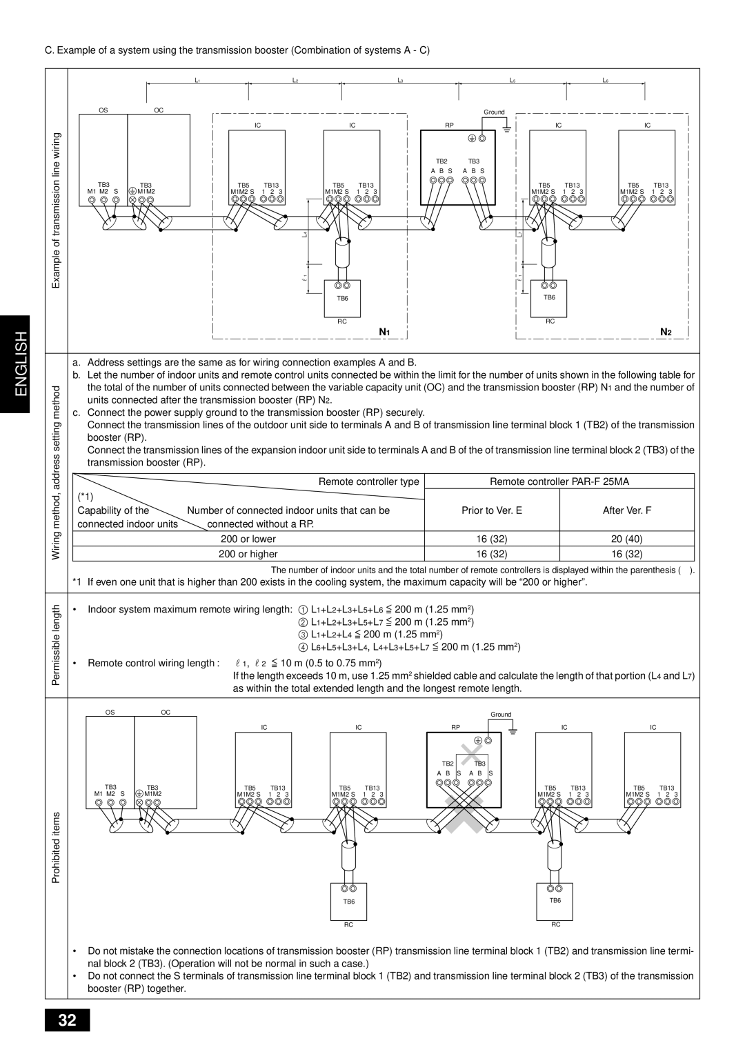
C. Example of a system using the transmission booster (Combination of systems A - C)
|
|
|
| L1 |
|
|
| L2 |
| L3 | L5 |
|
|
| L6 |
|
|
|
| OS |
| OC |
|
|
|
|
|
|
| Ground |
|
|
|
|
|
|
|
|
|
|
|
|
|
|
|
|
|
|
|
|
|
|
|
|
| |
|
|
|
|
| IC |
|
| IC |
| RP |
| IC |
|
|
| IC |
|
|
wiring |
|
|
|
|
|
|
|
|
| TB2 | TB3 |
|
|
|
|
|
|
|
line |
|
|
|
|
|
|
|
|
|
|
|
|
|
|
|
| ||
|
|
|
|
|
|
|
|
| A B S | A B S |
|
|
|
|
|
|
| |
transmission | TB3 |
| TB3 | TB5 | TB13 |
| L4 | TB13 |
| L7 | TB13 |
| TB5 | TB13 |
| |||
|
|
| TB5 |
| TB5 |
|
| |||||||||||
| M1 M2 | S | M1M2 | M1M2 S | 1 | 2 | 3 | M1M2 S | 1 2 | 3 | M1M2 S | 1 | 2 | 3 | M1M2 S | 1 | 2 | 3 |
Exampleof |
|
|
|
|
|
|
| r1 |
|
| r1 |
|
|
|
|
|
|
|
|
|
|
|
|
|
|
| TB6 |
|
| TB6 |
|
|
|
|
|
|
|
|
|
|
|
|
|
|
| RC |
|
| RC |
|
|
|
|
|
|
|
|
|
|
|
|
|
|
|
|
| N1 |
|
|
|
|
|
| N2 | |
| a. Address settings are the same as for wiring connection examples A and B. |
|
| |
| b. Let the number of indoor units and remote control units connected be within the limit for the number of units shown in the following table for | |||
method | the total of the number of units connected between the variable capacity unit (OC) and the transmission booster (RP) N1 and the number of | |||
units connected after the transmission booster (RP) N2. |
|
| ||
c. Connect the power supply ground to the transmission booster (RP) securely. |
|
| ||
setting | Connect the transmission lines of the outdoor unit side to terminals A and B of transmission line terminal block 1 (TB2) of the transmission | |||
booster (RP). |
|
|
| |
|
|
|
| |
address | Connect the transmission lines of the expansion indoor unit side to terminals A and B of the of transmission line terminal block 2 (TB3) of the | |||
transmission booster (RP). |
|
| ||
|
|
| ||
|
|
|
| |
method, | connected indoor units | Remote controller type | Remote controller | |
connected without a RP. |
|
| ||
| (*1) |
|
|
|
Wiring | Capability of the | Number of connected indoor units that can be | Prior to Ver. E | After Ver. F |
| 200 or higher | 16 (32) | 16 (32) | |
|
| 200 or lower | 16 (32) | 20 (40) |
|
|
| ||
|
| The number of indoor units and the total number of remote controllers is displayed within the parenthesis ( ). | ||
*1 If even one unit that is higher than 200 exists in the cooling system, the maximum capacity will be “200 or higher”.
length | • Indoor system maximum remote wiring length: | 1 L1+L2+L3+L5+L6 = 200 m (1.25 mm2) |
|
|
| |||||
|
|
|
|
| 2 L1+L2+L3+L5+L7 = 200 m (1.25 mm2) |
|
|
| ||
Permissible |
|
|
|
| 3 L1+L2+L4 = 200 m (1.25 mm2) |
|
|
|
| |
|
|
|
| 4 L6+L5+L3+L4, L4+L3+L5+L7 = 200 m (1.25 mm2) |
|
|
| |||
|
|
|
|
|
|
|
| |||
| • Remote control wiring length : | r1, r2 | = 10 m (0.5 to 0.75 mm2) |
|
|
|
| |||
|
|
| If the length exceeds 10 m, use 1.25 mm2 shielded cable and calculate the length of that portion (L4 and L7) | |||||||
|
|
| as within the total extended length and the longest remote length. |
|
|
| ||||
| OS | OC |
|
|
|
| Ground |
|
|
|
|
|
|
|
|
|
|
|
|
| |
|
|
| IC |
| IC | RP |
| IC |
| IC |
|
|
|
|
|
| TB2 | TB3 |
|
|
|
|
|
|
|
|
| A B S | A B S |
|
|
|
| TB3 | TB3 | TB5 | TB13 | TB5 | TB13 | TB5 | TB13 | TB5 | TB13 |
| M1 M2 S | M1M2 | M1M2 S | 1 2 3 | M1M2 S | 1 2 3 | M1M2 S | 1 2 3 | M1M2 S | 1 2 3 |
Prohibiteditems |
|
|
|
|
|
|
|
|
|
|
|
|
|
|
| TB6 |
| TB6 |
|
|
|
|
|
|
|
| RC |
| RC |
|
|
|
•Do not mistake the connection locations of transmission booster (RP) transmission line terminal block 1 (TB2) and transmission line termi- nal block 2 (TB3). (Operation will not be normal in such a case.)
•Do not connect the S terminals of transmission line terminal block 1 (TB2) and transmission line terminal block 2 (TB3) of the transmission booster (RP) together.
32