PUHY-YMC
Contents
Before installation and electric work
Safety precautions
Before getting installed
Before starting the test run
Before getting installed moved electrical work
Confirmation of parts attached
Combination with indoor units
Variable capacity unit Constant capacity unit
Outdoor unit configuration
Selection of installation site
Model Name Connecting pipe Elbow Shape
Space required around unit
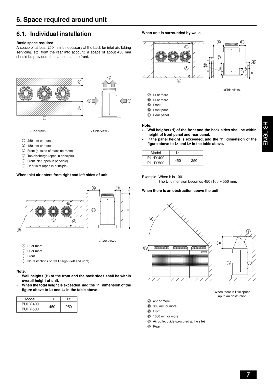
Individual installation
When inlet air enters from right and left sides of unit
When there is an obstruction above the unit
Collective installation and continu- ous installation
Lifting method and weight of product
Be very careful to carry product
Location of anchor bolt
Installation of unit
Installation
Example of collective installation
Noise level
Connecting direction for refrigerant piping
Down piping and down wiring precautions
60/61 dB A-weighted
PUHN-200/250YMC
Snow and seasonal wind
Countermeasure to seasonal wind
PUHY-400/500YMC
Areas of caution
Refrigerant piping installation
Never perform a pump down. This will damage the compressor
+ α
Refrigerant piping system
Multiple line/header
For variable capacity unit
Precautions concerning piping connection and valve operation
Figure shows valve fully open
Gas side Liquid side Oil balance side
60 to
50 to 57.5 / 500 to
75 to 750 to
100 to 1000 to Tightening angle standard Pipe diameter mm
Oil balance pipe connection method
Part could be damaged if not cooled sufficiently
Distributor gas connection method
Gram below
How to install branch pipe
Joint
Restrictions on the posture for attaching joints
Airtight test
Airtight test and evacuation
Evacuation
Thermal insulation of refrigerant piping
No heat insulation must be provided for electric wires
Inner wall concealed Floor fireproofing
Penetrations
Electrical work
Variable capacity unit
Control box and connecting posi- tion of wiring
Constant capacity unit
Transmission booster optional
For details, see item 11.3. Wiring transmission cables
Plate
Hole
Name, code and possible unit connections
Wiring transmission cables
Connecting a transmission booster
Wiring examples
Within Address Unit Remote control operation Same as above
Wiring method, address setting
Remote control RC terminal block TB6
One remote control unit for each indoor unit
For details, see wire connection example C
Main remote controller
Wiring Line
Same group to the remote control RC terminal block TB6
Unit Range Setting method
Extended length and the length to the most remote unit
Booster RP
Wiring
Capability Number of connected indoor units that can be
Wiring of main power supply and equipment capacity
Test run method
Operation procedure
Test run
Checking before getting test run
Abnormality
How to cope with test run abnormality
Flag 8 always lights
6603 Transmission error Transmission route Busy Error
Power on
Display at LED lighting blinking Remarks Flag Relay output
Coping with remote controller abnormality
Following phenomena do not represent abnormality emergency
NMK
Nkok
Nknk
Nkqk
NKPK#$%&*+
#$%&*+#,%&- ./0123145&6789#$%&=?@. !#
Sknk
#$% +,-.Ü
Skok
Uknk
TK=
Ukok
Ukpk Ukqk
Vkok
Nmknk =
NMK=
$%&*+,-./01
NMKOK=
#$%&*+QMã
NMKPK=L
Ãã ! k·ãLâÖJÅã
NMKQK=
#$%&#*#%+, -. !*#
NMKRK=
NMKSK=
#$%& *+& 012345678 .#$%&*+,-./0 1$%#234
NNKNK=
NNK=
NNKOK=
Rsrv
NNKPK=
#$% +,-./012
NRO
#$% +,-./0/12`kQN
=EqRF= !# $%&*+
Vwt
NNKQK=
NOKOK=
NOKNK=
NOKPK=
EptNF EibaF
NOKQK=
`ççäáåÖ EÉ~íáåÖ
Nokrk
NMK
Nknk
Nkqk
#$%&!*+
Sknk
Skok
TK=
Ukok
Ukpk Ukqk
Vkok
NMK=
NMKOK=
#$%&*+QMã
NMKPK=L
NMKQK=
#$%&#*#%+, -. !*#
NMKRK=
NMKSK=
#$%& *+& 012345678 .#$%&*+,-./0 1$%#234
NNK=
NNKOK=
NNKPK=
#$% +,-./012
NRO
#$#%&* +,-./0123456
=EqRF= !# $%&*+
NNKQK=
NOK=
NOKPK=
EptNF EibaF
NOKQK=
Nokrk
WT02922X02