Set-up and Installation Manual
Table of Contents
REV
118
Set-up and installation Overview
Flowchart
Product lineup
Cube installation
Safety precaution
Preparation
Input board installation optional
Unlocking for XL21
Color wheel unlocking
Lamp cushion removing for Changer
Cube stacking for Rear Assembling the base stands and cubes
PH50
Screen gap adjustment
Fixing to the wall and floor
Cube stacking for Front
Tape peeling off for
Screen detaching
Ventilation
For 67 , 50 Changer
For 50 Single
External AC fan attaching occasional
Assembling base stands and cubes
As needed, you can adjust the screen gaps
Adjustment
Screen open/close for Front
Screen opening
Screen closing
Connecting
Control signal connection
Image signal connection
Case of daisy chain
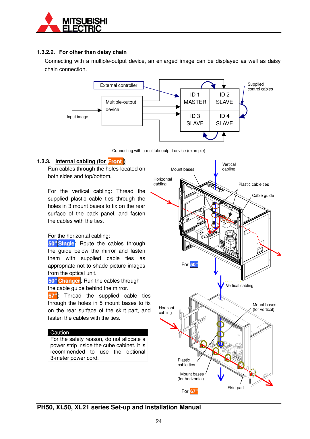
For other than daisy chain
Internal cabling for Front
Initial set up
Menu operation Control button list
Operation mode
Basic menu operation
Remote ID
Dipswitch setting
Picture outline adjustment
Displaying internal test pattern
Axis adjustment
Attaching
Front Close the screen .2.7.2, on
Adjustment
Detaching
Position Keystone Tilt Zoom
Correct the horizontal keystone distortion
Mirror adjustment
50 XL21
XL50 Rear and PH50
System memory setting
System set up Lamp Power
Lamp Mode for XL21 This adjustment is normally unnecessary
Terminate This adjustment is normally unnecessary
Start Memory
Overlap for the input board
Image Flip This adjustment is normally unnecessary
Baud Rate
System Sync
Indication This adjustment is normally unnecessary
Auto Power on
Extended ID
Resolution for PH50 This adjustment is normally unnecessary
Direction This adjustment is normally unnecessary
Cable Length for PH50 and XL50
Lamp Change for
Changer
Color balance adjustment
Black Level This adjustment is not necessary
REV
White Balance
Gradation
Target Color
Sensor
Image set up
Color Matrixuser
ADV.COL This adjustment is normally unnecessary
ADV.DARK This adjustment is normally unnecessary
Gamma This adjustment is normally unnecessary
Dither This adjustment is normally unnecessary
White Boost This adjustment is normally unnecessary
Input memory setting for the main input
Automatic input signal scanning
Input port selecting
Signal adjustment
3.1. H.POSITION, V.POSITION
Fine for Analog input
AMP Gain for Analog input
Signal Select for XL21
Signal Select
Clamp START=0, Clamp WIDTH=0. Procedure
Contrast
Brightness
Color Matrix
Aperture
Input memory saving
Input memory calling/deleting
Input memory setting for the input board
Expansion setting
4.1. H.POSITION, V.POSITION
Fine for S.ANALOG input
AMP. Gain for S.ANALOG input
Value is automatically set in automatic input signal
Scanning
Clamp START=0, Clamp WIDTH=0. Procedure
With VC-B20KA
Brightness
VCR Mode for Composite or Y/C input with VC-B20KV
ASPECT-RATIO
Color for Composite or Y/C input
Tint for Composite or Y/C input
Input memory saving
Display memory setting for the input board
Input Memory
2. H.DISPLAY POS, V.DISPLAY POS
Screen Mode
Digital OUT
Display memory saving
Display memory calling/deleting
Setting as daisy chain connection for the input board
Display POS /1
Regular maintenance 2.1. Lamp replacement
Safety precautions
Procedure
For Single
Tighten the two lamp fixing screws
For Changer
Open the lamp cover
Close the lamp cover
Partition door
Auto-lamp changing function for Changer
Action in lamp failure burnout or explosion
Action in brightness deterioration
Manual lamp swap
Lamp position auto calibration
Lamp will Exchange Soon
Condenser lens adjustment for Single
Focus adjustment
Cleaning
Cleaning procedure
Screen front surface
Cabinet
Filter Reset
Filter Time
Axis adjuster fixing
For delivery
Color wheel locking for XL21
Lamp cushion inserting for
Front
Screen-holding arm locking for 67 Front
Function Memories
Menu trees
Input memory
Common items
Additional items When Analog or S.ANALOG is selected
Additional items When S.DIGITAL is selected
Display memory
System memory
Items within parentheses are initial values
Memory list display
Test pattern list
Control panel
LED display
LED display list
Terminal functions
RS-232C terminal
Control terminal
Available input signal list RGB signal
Ycbcr Ypbpr component video signal
Motorized adjustment tool, S-AXL50E specification
Accessory
Applicable product
Outline drawing
Terminal for firmware upgrading/slide switch
Terminals Outline
Rotary dial
Reset button
Recovery procedure from error
Trouble shooting
LED
Adjustment software, Wallaby 4.1. General
Installation
Initial set-up
System configuration setting
Automatic panel ID setting
Manual panel ID setting
Serial port setting
Adjustment
Serial port opening
Turning on
Picture mute off
Service tab for system memory
Maintenance
Auto CSC function
Optimize gain function
Installation
Misc Function
Input tab for input memory
107
Additional items When Composite or Y/C is selected
Display tab for display memory
Memory tab
Information tab
Memory copy
Memory backup
Cube data saving
Data sending to cubes
Power and Mute
Main window
Panel selection area
Serial Port
Menu bar
Edit menu Read Parameter
Send Parameter
Copy Parameter
Paste Parameter
System Config menu By n 1x1, 2x2, 3x3 or
Other Wall Config…
Cube ID Setting
Auto ID
Port Setting
Special menu Protect Setting
Serial Port menu Log…
Open
About trademarks
Revision history
Description Revision date